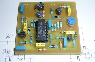
Recent fun-and-games with copies of the Ibanez Tube Screamer guitar overdrive pedal have got me interested in its function to the extent that I've made an analysis of its small-signal frequency response...
![]()
Anybody who is discouraged by maths can scroll past ugly equations - there are results of measurements and Spice simulations lower down in this post! You might also find this excellent description of Tube Screamer behaviour more to your taste.
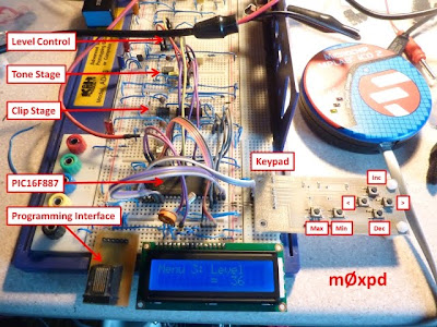
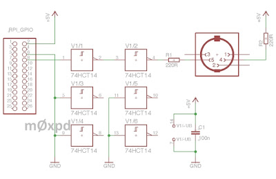
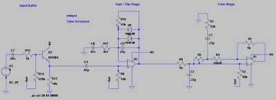
Readers might find the suggestion that linear circuit analysis of the behaviour of an inherently non-linear device is worth performing or reporting ironic. However, one of the defining and differentiating features of the Tube Screamer is precisely the filtering operations it applies to the guitar signal (and non-linear functions thereof). Accordingly, understanding the linear aspects of this "urban legend" is useful - we start with consideration of the "Tone" stage...
![]()
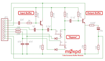
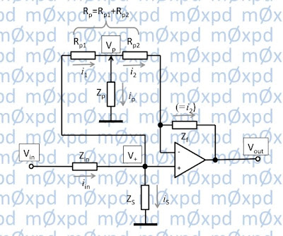
This circuit is a (fairly) conventional first-order HF shelving network - adjusting the tone control boosts or lifts the high frequency content of the input signal. However, the presence of the 220nF in the low-pass filter seen in the dashed red box above complicates the circuit - so my analysis is needed. To keep the algebra tidy, I've simplified the picture somewhat (by replacing the paralleled 220nF and 10 kOhm resistor on the input by a single impedance ZS and by replacing the series 220 nF capacitor and 220 Ohm resistor between the potentiometer wiper and ground by a single impedance ZP).
It is also necessary to name some nodes and currents, to which the analysis will refer...
![]()
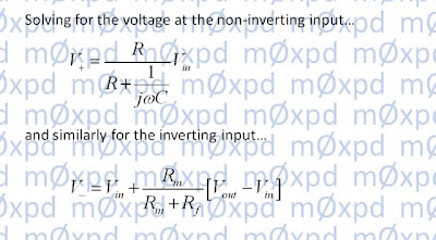
The first step in analysing the tone filter is to establish a relationship between the voltage on the tone control potentiometer wiper and the op-amp input(s)...
![]()
This relationship will be used in the subsequent solution, so we're giving it a name: "X"...
![]()
Notice that X includes some fixed elements (like the impedance ZP and the total resistance of the tone potentiometer, RP. However, X importantly includes a variable element, Rp1Rp2 ; X is a function of tone control setting.
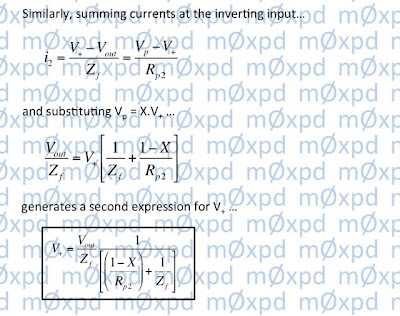
Our analysis proceeds by considering the currents at the op-amp inputs...
![]()
![]()
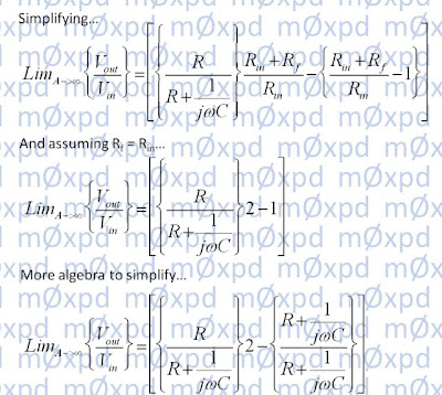
which leads us to a solution for the frequency response of the Tone stage...
![]()
Notice that this solution includes 'X' (which we already know to be a function of tone control setting). The solution in the form above is also itself an explicit function of tone control setting, through the presence of Rp1 and Rp2.
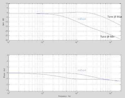
The response of the tone control stage alone is shown in the Bode plot below (produced in MATLAB, by evaluating the solution shown above). The result shows the tone response with the tone potentiometer in extreme positions...
![]()
Having solved for the response of the Tone stage, it is simple to go on to develop a solution for the overall frequency response of the Tube Screamer (at least in the small-signal context below the signal amplitudes that start to introduce distortion). Analysis of the "Clip" stage is actually easier than that for the Tone stage...
![]()
In the analysis which follows, we assume that the voltage over the diodes is lower than their forward turn-on threshold, in which case they can be ignored. The high-pass filter in the dashed red box of the figure above is loaded only by the very high input impedance of the op-amp's non-inverting input. We can, therefore, obtain its frequency response using the potential divider rule. Thereafter, the op-amp is in standard non-inverting configuration, such that its response is given by a familiar simple rule. The Clip stage small-signal behaviour can be written immediately as...
![]()
Various commentators have spoken of the action of the Tube Screamer being largely derived from the fact that the clip stage passes a mixture of the un-processed guitar sound plus the distorted sound - this is seen in the sum in the square bracket of the equation above. I confess that I'm not sure how useful this distinction actually is to understanding the system - particularly as Zf/Zin> > 1.
Now we have small signal responses of the Clip and Tone stages, we can multiply them together to get the overall response of the Tube Screamer (as shown in the equation at the top of this post). But who's to say my analysis is right?
Fortunately, there are ways to check it...
First, we can follow the lead of others and perform Spice analysis of the system...
![]()
Second - and much more interestingly, we can make measurement of an actual Tube Screamer (or, at least, one of my new clones) and compare the result. The graph below shows the magnitude frequency response of the Tube Screamer's small-signal (linear) behaviour, at extreme tone settings. Three traces are shown - one for my analysis, one for Spice modelling and one for actual measurement. You can see they overlay each other, equal (to within expected errors)...
![]()
The "Analysis" result in the graph above also includes a few high-pass responses, not described in the text. These are associated with (e.g.) the input and output buffers (implemented by emitter followers in the Tube Screamer) and have very low frequency corner frequencies.
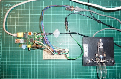
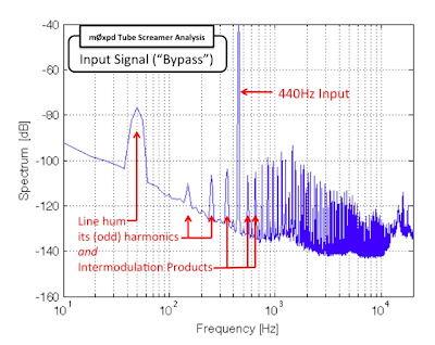
Having spent effort avoiding non-linearity (such that Fourier and Laplace have something to contribute to a small-signal analysis), I took the opportunity presented by having the Tube screamer (clone) connected to some heavy-weight analysis gear to record some of the system's non-linear behaviour...
I generated a 440Hz sine-wave test input. Non-musical readers may remember that 440Hz is an important frequency reference that used to be broadcast on BBC2 with the test card, before wall-to-wall daytime television crowded out the schedule. More musical readers will know that 440Hz is "Concert A"...
![]()
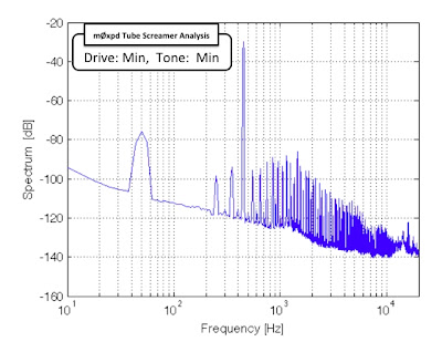
With the drive control and tone control on minimum, the output produced in response to the 440Hz input is little different...
![]()
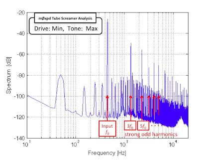
Turning the tone control to "Max" allows strong odd-order distortion products through to the output...
![]()
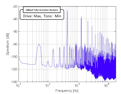
With the drive control on "Max", but tone backed off to "Min", there are still strong odd-order overtones produced...
![]()
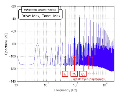
Finally, pushing everything up to eleven boosts the strong odd-order products and also allows some even-order distortion products to be seen...
![]()
OK - that's enough building, simulating, analysing and measuring. I really ought to be playing.
...-.- de m0xpd

Anybody who is discouraged by maths can scroll past ugly equations - there are results of measurements and Spice simulations lower down in this post! You might also find this excellent description of Tube Screamer behaviour more to your taste.
Readers might find the suggestion that linear circuit analysis of the behaviour of an inherently non-linear device is worth performing or reporting ironic. However, one of the defining and differentiating features of the Tube Screamer is precisely the filtering operations it applies to the guitar signal (and non-linear functions thereof). Accordingly, understanding the linear aspects of this "urban legend" is useful - we start with consideration of the "Tone" stage...

This circuit is a (fairly) conventional first-order HF shelving network - adjusting the tone control boosts or lifts the high frequency content of the input signal. However, the presence of the 220nF in the low-pass filter seen in the dashed red box above complicates the circuit - so my analysis is needed. To keep the algebra tidy, I've simplified the picture somewhat (by replacing the paralleled 220nF and 10 kOhm resistor on the input by a single impedance ZS and by replacing the series 220 nF capacitor and 220 Ohm resistor between the potentiometer wiper and ground by a single impedance ZP).
It is also necessary to name some nodes and currents, to which the analysis will refer...
The first step in analysing the tone filter is to establish a relationship between the voltage on the tone control potentiometer wiper and the op-amp input(s)...

This relationship will be used in the subsequent solution, so we're giving it a name: "X"...

Notice that X includes some fixed elements (like the impedance ZP and the total resistance of the tone potentiometer, RP. However, X importantly includes a variable element, Rp1Rp2 ; X is a function of tone control setting.
Our analysis proceeds by considering the currents at the op-amp inputs...

which leads us to a solution for the frequency response of the Tone stage...

Notice that this solution includes 'X' (which we already know to be a function of tone control setting). The solution in the form above is also itself an explicit function of tone control setting, through the presence of Rp1 and Rp2.
The response of the tone control stage alone is shown in the Bode plot below (produced in MATLAB, by evaluating the solution shown above). The result shows the tone response with the tone potentiometer in extreme positions...
Having solved for the response of the Tone stage, it is simple to go on to develop a solution for the overall frequency response of the Tube Screamer (at least in the small-signal context below the signal amplitudes that start to introduce distortion). Analysis of the "Clip" stage is actually easier than that for the Tone stage...

In the analysis which follows, we assume that the voltage over the diodes is lower than their forward turn-on threshold, in which case they can be ignored. The high-pass filter in the dashed red box of the figure above is loaded only by the very high input impedance of the op-amp's non-inverting input. We can, therefore, obtain its frequency response using the potential divider rule. Thereafter, the op-amp is in standard non-inverting configuration, such that its response is given by a familiar simple rule. The Clip stage small-signal behaviour can be written immediately as...
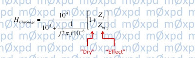
Various commentators have spoken of the action of the Tube Screamer being largely derived from the fact that the clip stage passes a mixture of the un-processed guitar sound plus the distorted sound - this is seen in the sum in the square bracket of the equation above. I confess that I'm not sure how useful this distinction actually is to understanding the system - particularly as Zf/Zin> > 1.
Now we have small signal responses of the Clip and Tone stages, we can multiply them together to get the overall response of the Tube Screamer (as shown in the equation at the top of this post). But who's to say my analysis is right?
Fortunately, there are ways to check it...
First, we can follow the lead of others and perform Spice analysis of the system...
Second - and much more interestingly, we can make measurement of an actual Tube Screamer (or, at least, one of my new clones) and compare the result. The graph below shows the magnitude frequency response of the Tube Screamer's small-signal (linear) behaviour, at extreme tone settings. Three traces are shown - one for my analysis, one for Spice modelling and one for actual measurement. You can see they overlay each other, equal (to within expected errors)...

The "Analysis" result in the graph above also includes a few high-pass responses, not described in the text. These are associated with (e.g.) the input and output buffers (implemented by emitter followers in the Tube Screamer) and have very low frequency corner frequencies.
Having spent effort avoiding non-linearity (such that Fourier and Laplace have something to contribute to a small-signal analysis), I took the opportunity presented by having the Tube screamer (clone) connected to some heavy-weight analysis gear to record some of the system's non-linear behaviour...
I generated a 440Hz sine-wave test input. Non-musical readers may remember that 440Hz is an important frequency reference that used to be broadcast on BBC2 with the test card, before wall-to-wall daytime television crowded out the schedule. More musical readers will know that 440Hz is "Concert A"...
With the drive control and tone control on minimum, the output produced in response to the 440Hz input is little different...
Turning the tone control to "Max" allows strong odd-order distortion products through to the output...
With the drive control on "Max", but tone backed off to "Min", there are still strong odd-order overtones produced...
Finally, pushing everything up to eleven boosts the strong odd-order products and also allows some even-order distortion products to be seen...
OK - that's enough building, simulating, analysing and measuring. I really ought to be playing.
...-.- de m0xpd