Quantcast
Channel: m0xpd's 'Shack Nasties'
Viewing all 220 articles
Browse latest View live

Enigmatic déjà vu

$
0
0
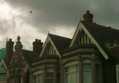
I was lucky enough to find myself once again in striking distance of Bletchley Park yesterday and enjoyed another interesting visit. Just like last time, the Battle of Britain Memorial Flight treated us to a fly-past - this time by a Spitfire...


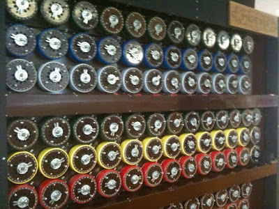
Having last time focussed much attention on Colossus, I was determined to spend a little more time looking at the Bombe (which itself has been the subject of a re-build project) ...


I was fortunate to be able to chat with one of the guides, who explained in considerable detail the operation of this impressive machine. I don't know her name or her background, but she certainly understood operation of the Bombe in depth and I am grateful for her expertise.

Talking about expertise, I was pleased to chat once again with David Wright, g3zpa, who gave me some more information about the original (long-wire) antenna systems supplied for use with the Paraset.

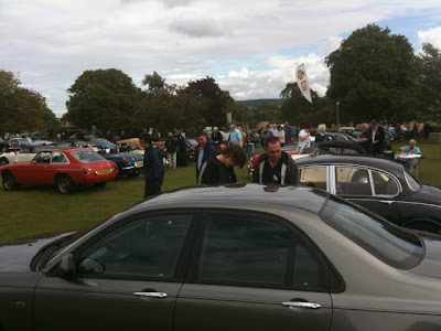
In addition to the aircraft flypast, there was an impressive gathering of classic cars with the inevitable superabundance of MGs (I'm allowed to say that as an MGB owner)...


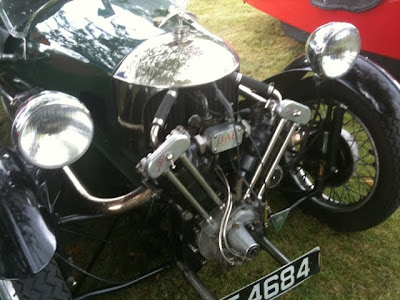
However, other marques were well represented too. The car of the show (for me at least) was a drop-dead-gorgeous Alfa Giulia Veloce - but I was pleased to see some nice 3-wheeler Morgans...


These 3-wheelers are of interest partly because the XYL's grandfather used to own one and partly due to their pivotal role in the plot of Dorothy Leigh Sayers' "Have His Carcase". Morgans more generally have a place in my heart as the XYL and I went on honeymoon in a 4-4. Happy days!

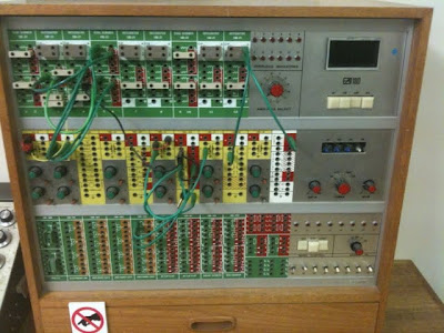
Cars and aeroplanes aside, there was lots more to interest me at BP - not least in my first visit to The National Museum of Computing which, appropriately, is in the same building as Colossus. After seeing the PDP8's of my youth I was pleased to see a healthy display of analog computers (which - for those of you who don't know - solve differential equations by electrical ANALOGY) amongst which was something I'd never seen before: a hybrid analog AND digital computer...


In truth, it was an analog computer with a few digital elements (flip-flops etc) along the bottom "row" in the photo above.

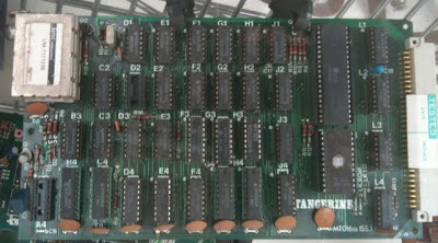
I was also delighted to find an example of the main board from a Tangerine "microTan 65"...


One of my first computers was built around this 6502-based system marketed as a kit by Tangerine. There was a basic interpreter, a disk operating system and all sorts of goodies. Nice to see it again!

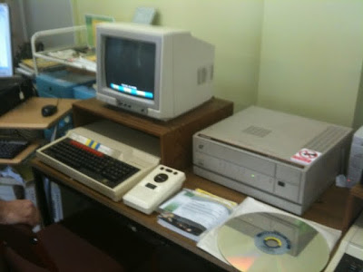
However, the high spot of my visit to the National Museum of Computing was certainly the Domesday systems, based on BBC / Acorn hardware and in the news recently because of the "Domesday reloaded" initiative. Here's one of the two working systems at BP...


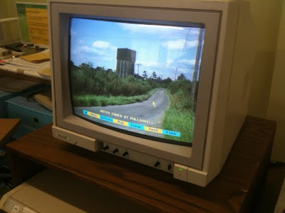
We were staying with the in-laws, near Pulloxhill, Beds., so we used the amazingly modern multi-media interface to search for Pulloxhill and pulled up a picture of the characteristic water tower...


Here's a link to the photo on the web-based Domesday Reloaded resource.

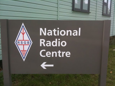
Partly (I am told) in consequence of the recent financial debacle at the RSGB, the new radio centre isn't yet open to visitors...


... but we did call into the MKARS club house (in an old generator building on the BP "campus") where I had a nice chat with Graham, a G7 licensee (I missed the rest of his call), before driving back to Pulloxhill.

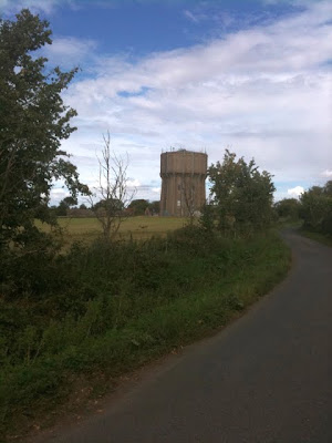
On the drive back we stopped to take an up-to-date shot of the water tower...


Sitting outside drinking a cup of tea half an hour later, the day was crowned by an unexpected flypast of a Consolidated Catalina, the conspicuous lines of which were unmistakable even at altitude...


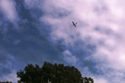
I assume she was G-PBYA, which is "berthed" at Duxford - she certainly was heading in the right direction!

Perfect end to a(nother) grand day out!

...-.- de m0xpd

Appreciation as Grabber Goes QRT

$
0
0
A few days ago on the KnightsQRSS Mail List Johan, on5ex, announced that his excellent QRSS grabber is soon going QRT.

Johan and his grabber have been giving wonderful service to me and to many QRSS operators for many years. In fact, it was Bill Meara's talk of this mysterious station up in Belgium picking up signals from The Eternal City which started my interest in QRSS.

Johan became the second station to report seeing my own QRSS signals and has been picking me up ever since (including back in the day when my Hellschreiber was UPSIDE DOWN!!).

So - now its time to say a huge THANK YOU to Johan and to wish him every success in his new games with other radio modes.

73 dr OM Johan,

...-.- de m0xpd

Italian Job in Toytown

$
0
0
The XYL's father is something of a model railway enthusiast - the photo below reveals the ironic understatement...


During our last visit (in which I took the photo), he asked me to make a traffic light controller - no doubt in an attempt to bring order to the anarchic road-rage one otherwise meets at a 1:76 scale crossroads.

Of course, a traffic light controller is a pretty trivial problem in Finite State Machines 101, so I quickly whipped up a system based on a PIC16F676, with on-board LEDs to monitor progress and open collector outputs to switch on and off the "grain-of-wheat" bulbs which the Toytown traffic engineers have used.

Here's the system under prototyping, connected to my PICKit2...

and here's the translation to a PCB...


All pretty dull. So I decided to fool around a little...

Readers will remember the havoc that can be wrought by messing with traffic lights, as demonstrated in the movie classic "The Italian Job".


I decided it would be fun to introduce an occasional state of confusion in the traffic signals on my father-in-law's railroad - so I programmed in a display which would look good on the Golden Mile...


(Interesting how the video - captured by my iPhone in low light conditions - is incapable of resolving the colour of the bright monitor LEDs)

The traffic light chaos only kicks off every 200 complete cycles, so you have to be watching the lights (or driving past at just the wrong moment in a 1:76 scale car) to see it.

Let's see if he notices!

...-.- de m0xpd

Heavy Artillery

$
0
0
The same sale of surplus gear that bumped up my BNC socket stocks also saw me bid a tenner to win a wideband RF power amplifier, which runs 12 Watts, 200 kHz - 32 MHz, made by RF Power Labs, Inc. of Kirkland, WA. It had Albert, G3ZHE's sticker on it, so I knew it had come from a good home. Albert told be that previously it had been in Jim G3NFB's shack - it is nice to be keeping it in the Warrington family!

Today, I had chance to power it up and see what it does...

I hooked it up between the output of my multi-mode beacon (Blogs passim), which happened to be set to the 30m band, and the G5RV. Here is the "brick" on the bench...


You can just see one of my switched attenuators atop the amplifier, throwing away some of the input (the amplifier needs 1 Volt in for full rated output).

I was immediately spotted on WSPR in the USA by Edmund, WB1FIG, in Plainville, Massachusetts...

having previously only been heard in Europe.

I do get into the US on occasion with the standard 50mW on 30m, as demonstrated last night, when Douglas, W3HH, heard me once again in Florida...

Having fired WSPR signals over the pond with my new "big gun", I had a look to see if my other modes were being heard further afield. Sure enough, I could just make out my FSK-CW and Hell signals on Bill, W4HBK's grabber in Florida (although you do need to know where to look)...


Of course, the QRSS modes into Europe were loud and clear, as seen on Joachim, PA1GSJ's grabber...


In fact, Joachim was also reporting spotting my WSPR signals both during and after the 5 Watt QRO test. Switching from 5W back to 50mW is a x100 change in power (-20dB) and, sure enough, Joachim's reports showed pretty much a -20dB degradation in SNR between two adjacent spots...


So - the bench RF amplifier works a treat.

Apologies to anybody offended by the fact that I couldn't be bothered to change reported power in my WSPR message during the short test - it is a chore re-programming the PIC - mea culpa!

...-.- de m0xpd

A Splendid Jaunt

$
0
0
Just back from a few days in the beautiful surroundings of Pickering, North Yorkshire, where we stayed in a delightful cottage conveniently positioned mid-way between a trout lake and a railway station - the very 'gate of heaven'!


Whatever Kirstie and Phil might bang on about, this establishment didn't just rest on its location laurels - it was beautifully presented as well. In addition to the little two-bedded cottage in which we stayed,"The Limes", the good folks at High Mill also have a larger property for rent, which sleeps up to 12.
The view from my armchair was fantastic - here's 7F 0-8-0 heavy duty freight locomotive 49395 working a passenger service tender-first back to Grosmont...


We took the same trip ourselves a few days later, travelling back from Grosmont in fine style in the first class observation saloon at the end of a nice rake of wooden LNER coaches (you can see the new Barbour Beaufort I got from the Orvisstore on Pickering's Market Place hanging over the back of my armchair)...


The staff at the Orvis store deserve special mention as they honoured the "£20 off" voucher that came with our railway ticket, even though I'd purchased the coat two days before!

Things took a turn for the better when some thoughtful chap came and offered us drinks - here's my "Gin and Tender"...


(the tender being that of the 9F engine 92214 "Cock O' The North", which strained and sighed on the other side of the glass whilst pulling us back to Pickering).

Here's the observation saloon from the outside on reaching the shelter of Pickering Station's new roof...


Aside from many other notable delights (Gannets at Bempton, the Castle atop the hill behind High Mill and a sublime piece of rib-eye steak at The White Swan), the trout lake served up its usual entertainment...


I think it is actually bigger than the one caught in April - certainly your humble servant looks pretty pleased with himself...


If you want a break in a great location, give High Mill a try - seen here photographed from the observation saloon...


I certainly will be going back.

The only fly in the soup was the trouble I had getting any signal out (2W on 40m CW from the FT817 and Whip). Still, the Mill is on a road called the "Undercliffe" - the clue's in the name!

...-.- de m0xpd

Requiescat in Pace

$
0
0
Saddened to hear news of the death of Anthony Edgar "Tony" Sale, whose work on the rebuild of Colossus was central to the preservation of Bletchley Park and the establishment of The National Museum of Computing.


Tony was there tending his creation when I visited Colossus last year - he leaves a legacy not only in the physical rebuild of the machine, but also in the enthusiasm he fostered in a team of colleagues who helped with the rebuild and now ensure the preservation of some important pieces of history.

...-.- de m0xpd

Most Secret War

$
0
0
Just finished reading R.V Jones' autobiographical book "Most Secret War, British Scientific Intelligence 1939 - 1945"...


being an account of his work as leader of the Air Ministry's Scientific Intelligence Section in WW2. In short, the book is a masterpiece and a must-read for anybody remotely interested in some of the technological and scientific tussles between the allies and the Third Reich.

I purchased the book during my last visit to Bletchley Park and there is obligatory mention of the activities of the Code-Breakers in providing the most reliable of data streams for the Scientific Intelligence community in the UK - an "anchor of truth", as the author describes it (p 530).

There is much else to entertain those with radio-related interests - including the detection, understanding, prediction and ultimate jamming of the radio navigation beams by which the Luftwaffe we able to achieve accuracy in their bombing activities and the similar location, interpretation and jamming of the radar systems which allowed German night-fighters to engage Bomber Command missions over Germany. However, beyond these triumphs, it was the author's involvement in the development and deployment of the countermeasure we now call "Chaff" - then inexplicably known as "Window" - which impressed me most.

This is a giant of a book, fully deserving the hyperbolic notices which adorn its paperback cover ("Among the best of all war books", "Every bit as good as a Deighton or Le Carre Yarn").

Yes - this deserves to be read. Unfortunately, in reading it, I found myself admiring Dr Jones' achievements but becoming anything but warm toward him as a person. Perhaps that's a by-product of the determination and single-mindedness that made him so successful in his great work.

What would I give for determination and single-mindedness?

Not a lot!

...-.- de m0xpd

Shelving Audio Filter

$
0
0
I was fortunate to pick up a Leslie 825 speaker for my virtual organ project (Blogs passim) for a song on eBay...


Part of the explanation for the attractive price was that - as the seller put it - this is "a Leslie 825 speaker with a difference".

I'll let the seller go on with his description:

"the difference is that the (previous) owner had a number of keyboards and he modified the cabinet by inserting two other speakers front and back - he drilled holes in the cabinet and placed a grill over the front - the grill is available but is not in the picture so that you can see what lurks beneath".

Well, now YOU can see the ugly array of holes in the picture above. I have fixed the grille on to make thinks look a little less unsightly and, like the seller, I haven't yet bothered to test the additional speakers. But the Leslie itself works well enough (with one trivial exception, to be described below).

For those of you who don't know, a Leslie speaker includes rotating mechanical elements (horns and/or baffles) to introduce a cyclical variation to the radiation from the loudspeaker which, in interaction with the acoustics of the performance / listening space, makes some interesting spatial audio effects involving amplitude and frequency modulation and comb filtering. It was developed by Don Leslie...


in an attempt to emulate the chorus effect produced when ranks of (inevitably somewhat de-tuned) organ pipes speak together, giving electronic organs a "pipe voice". The mechanical components are contrived to rotate at one of three different speeds (slow/stop/fast or, to respect the orthology, chorale/stop/tremolo) under the control of the iconic "half-moon" switch. Paul, g1dva, tells me he has seen rotating speakers with continuously variable speed control - but we'll dismiss these as pathological. Certainly, the classic Leslie only operates at a few discrete speeds, latterly the three described above.

Older Leslies used a horrible electrical interface, in which mains power, control signals and the audio were all applied through a long, multi-way cable terminated with special (i.e. expensive) Amphenol connectors. In the case of the 825, it is a 9-pin system, with the following connections...

PinColourFunction
1BlackGround
2RedInput
3YellowNo Connection
4OrangeStationary Input / Aux Control (not used in 825)
5Greendc Output (+28V)
6WhiteSlow Motor Control
7VioletFast Motor Control
8Gray240V In
9Blue240V In

(The colours are those of the cores of the "official" Leslie Cables).

The seller of my 825 kindly gave me a 9-pin cable to connect up the device - thanks Bob!

Well, I had the cable but no socket for the organ end, so I lashed things together with a very unsafe Heath Robinson connection, involving individual pieces of "Choc Bloc" connector...


on each of the pins of the plug - DO NOT TRY THIS AT HOME, CHILDREN!

All this gave me opportunity to confirm that the speaker was working, to bask in the glorious spatial effects of a real Leslie (emulations only work up to a point) and - after the honeymoon was over - to become disappointed with the sound!

The 825 has no horn (and associated HF unit) - only a large "full-range" speaker firing through a rotating drum. In consequence the top end is hardly what might be described as "sparkling". In fact it is so poor that I began to think there was something wrong with the "key click" function in the fantastic VB3 software and I actually contacted the programmer before realising that the problem lay right there in my new 825 - sorry Guido!

All this led to some creativity - I acquired a 9-pin socket to replace the temporary lash up (thanks George) and I decided to build a filter to boost the HF response and try to rescue some of the sound. The (sound card) output from my virtual Hammond wasn't enough to drive the speaker to satisfactory levels, so a Pre-Amp stage with some gain was indicated too.

Here's my HF shelf filter, seen as an extract from the LTSpice simulation of the entire circuit...


The series combination of R5 and R6 was actually realised with a potentiometer, configured to give me a variable HF lift. Here's the magnitude response simulated in LTSpice for an arbitrary setting...


The lift above 1kHz is the "shelf", made into more of a "bump" by the low-pass corner (deliberately) introduced by R1||C4.

I turned the idea into reality in a nice sloping front RS box, picked up at a rally somewhere, intentionally copying the format of the Leslie "Combo" Preamp. Here are the innards...


and here's a view of the back panel...


In addition to the variable high frequency shelf, there is an internal jumper to select 0, 10 or 20 dB overall gain and an external volume control. I haven't had chance to fit knobs to the controls yet!

There is (as is usual) a fly in the soup - the "d.c. output" from my new Leslie (pin 5) isn't working. I looked at the schematic and there is little to go wrong (I suspect a dead diode, D14, or an open connection), as the d.c. comes straight from the power supply to the amplifier driver stage, which most emphatically IS working! Still, at the moment, my new PreAmp is powered from a PP3 battery.

Result - FANTASTIC. The 825 is totally transformed and a pleasure to use.

I have some rather more exciting Leslie-related stories to tell - but they can wait for another day.

For now, I'm all in a spin!

...-.- de m0xpd


Update: Fly Rescued from Soup!

This evening I made up a shorter cable for the 825 - having 30 feet of cable coiled up is a recipe for trouble, not to mention hum. I so doing, I discovered that the 28Vdc issue isn't a speaker fault at all - just an intermittent connection in the long cable. The shorter one is fine (with new connectors) so now the PreAmp is powered from the Leslie as planned.

Pedalling like Fury

$
0
0
I was fortunate to pick up an old, worn, dirty set of Hamond C3 padals on eBay for a fiver back in August. Here they are at the start of the "resurrection" process...


After a lot of elbow grease (most of it from my wife, who generously contributed her domestic skills and cleaning products) the pedals looked much cleaner. They also worked rather better, as I had replaced any badly worn felts, some of which support each pedal laterally between vertical guide pins. Finally, I had stripped off the galvanized brackets which support the operating "tabs" which do the actual switching in the real Hammond Organ (which is why this is a "resurrection" rather than a "restoration").


From this angle, perhaps you can see why I believe the previous owner(s) preferred playing in the key of F!

I wanted to use these pedals in my virtual organ project (Blogs passim), which meant that they had to be able to operate as electrical switches rather than hinged pieces of wood. There are a few technology options here for the organ builder:
  • you could arrange for each pedal to touch and operate a miniature switch as in this example
  • you could make electrical contact pairs (or one contact per pedal and one or more busses) for each pedal and make a physical switch as in this example.
  • you could use an optical method, with a "shutter" tab on each pedal and a opto-detector making the translation from optical intensity to an electrical switch function
  • you could use a magnetic method, placing a magnet on each pedal and using a Hall Effect sensor adjacent to each pedal to convert the magnetic field to an electrical switch function
  • you could usea magnetic method, placing a magnet on each pedal and using a reed switch adjacent to each pedal to convert the magnetic field to an electrical switch function as in this example
There are examples of each of these methods on the internet.

I wanted to use the Hall Effect method, but I couldn't find the sensors cheaply enough (you should know me by now), so I stuck with the trusty, cheap reed switch technology...


I put 3mm Neodymium rod magnets into a hole drilled in the end of each pedal...


You can see the vertical guide rods and the felts, mentioned previously.

I also made up a series of perspex panels (chosen for its transparency, which made alignment with the magnets during "marking up" and subsequent assembly easy), each holding five or seven reed switches. I made brackets to support these panels, mounting under the nut and lock washer that secured the guide pins - the whole process involved no "butchery" of the pedals, except the magnet holes. One of the (five switch) panels is seen, in-situ, below...


I have described previously how my single-octave pedals were wired up and converted to MIDI. The same process was used again - with one significant exception...

The pedals are scanned as a matrix of (4) columns and (7) rows, the last having only one pedal (25 notes takes 6 rows of 4 and a single "extra"). In the previous encoder system, it was known that you could not play more than one pedal in a single column together whilst playing another pedal from another column without the possibility of additional notes sounding. This wasn't seen as a problem as playing two pedals in one "column" constitutes an interval of a minor third or less, which isn't done in the bass register (it is psycho-acoustically and musically meaningless).

However, the geometry of the new pedalboard made it easier for me to arrange that the reed switches should be normally on, switching to open circuit when a pedal is depressed. This meant that, from the point of view of my encoder scheme, all the notes in every column were being "played" most of the time - the system didn't work!

The solution is well-known and simple - you just add diodes in series with each reed switch et voila. Of course, I had to invert the logic of my encoder program (to send a "Note On" command when a reed went open circuit and vice-versa) but that was the work of moments.

Here's the expanded version of my pedal encoder system, capable of running 25 keys (plus seven spares for "toe pistons" or whatever) and the expression pedal...


The trouble with a two octave pedal board is that you need a real organ bench to sit "over" the pedals. Fortunately, eBay came to the rescue again, with a genuine Hammond A-100 bench...


I'm very surprised how easily this went together - I was frightened that the reed switches would be very difficult to set up, but they were easy. Careful location of the magnets (using a jig to drill the pedal ends) and equally careful marking up of the perspex carriers made it work first time.

All I need to do now is get out of the habit of stopping at that formerly top - now middle C!

...-.- de m0xpd

More Matters Enigmatic

$
0
0
It has been so long since my last post that part of me feels like making an apology - but the bigger, better part reminds me that this is for my pleasure and recognizes the potential danger of becoming ruled by a compulsion to blog, so I'll continue as if nothing has happened...

Amongst the many nice gifts I received at Christmas was a(nother) book about Bletchley Park, to add to those already devoured (some of which are reported elsewhere in these ramblings).

This time, it is Sinclair McKay's book "The Secret Life of Bletchley Park"...


This was a pleasant-enough read, different from all the other technically focussed books in that its subject is very much the people at BP and the context in which they served. The book looks at social, domestic and human aspects, without spending much time on the cryptanalytical methods and technologies at the core of the work. Also - unusually - the book doesn't become too distracted by the "celebrities", affording equal weight to some of the humbler folk on which the activities depended.

McKay describes the experiences of those who worked at BP, drawing heavily on other published materials and (apparently) a few interviews with veterans. We are given a glimpse of working conditions, billeting arrangements, recreational and cultural activities, romances between staff members and dealing with the imperatives of secrecy - both during and after the war. The book concludes with some descriptions of how BP veterans dealt with the changing conditions after the hostilities and attempts a brief sketch of the broader legacy of the work at Bletchley Park.

It is a rewarding read, but might have been better edited, not least to avoid an irritating sense of repetition. The book tries to assess the broader legacy of BP's work and occasionally is marred by repetition. [ed: scratch that - you've said it already]

Whilst we're adjacent to the subject of "Enigma", may I commend to the attention of British readers the weekly "Enigma Code" puzzle in our beloved "Radio Times"...


I'm no puzzle junkie, tending to sneer at Sudoku addicts, but this particular game interests and entertains me.

It takes the form of a "crossword without clues", in which all the squares are numbered with integers corresponding to the letters of the alphabet. Your task, should you decide to accept it, is to associate numbers and letters!

Give it a try - I saw a fellow passenger on a flight doing the same type of quiz from a different newspaper recently. I don't know which paper it came from, but I can confirm there are more of these puzzles out there if you become hooked.

Fortunately, I'm not the addictive type!

...-.- de m0xpd

Top Totty

$
0
0

Isn’t it heart-warming to know that, despite the imminent threat of economic Armageddon, with all its collateral, our politicians still have time and energy to devote to matters of grave import.

I understand from her website that Kate Green MP twitted (sic) to the effect that Slaters’ branding for their blonde beer ‘demeans women’. Although her actions can hardly further demean the laughing stock that is the political class, Ms Green undoubtedly has demeaned the cause of equality.

I have the good fortune to live in Ms Green’s constituency. Evidently, I do not have the good fortune to have my views “represented” (in any sense) by the local MP.

Cheers Kate!
...-.- de m0xpd

In a Spin

$
0
0
Aside from admiring, owning and using them, your humble servant is now active within the global economy of Leslie Speakers, having jointly developed an accessory which is commercially available. More of that sordid, mercenary semi-professionalism later. First, true to my Ham credentials, I'd like to share some details of my new Leslie interface, just for the love of it.

Readers have learned how I got my first Leslie, an 825, from Bob, just down the M56 in Chester. A couple of weeks before Christmas, I got another Leslie from another Robert, a little further west in Holywell. I'm pretty sure that the relative remoteness of Chester and (particularly) Flintshire kept the prices down to my beer-budget levels.


The new (old) Leslie is a 125 - similar to the 825 in that is has only a single speaker (but that's about to change - watch this space). The 125 is, however, critically different in at least three important respects. Firstly, it has a veneered wooden enclosure (rather than the ugly "Tolex" vinyl covering of the ProLine 825) - it LOOKS like a Leslie. Secondly, it has a valve(/tube) amplifier, with all the romance that entails. Thirdly, it uses a different interface to the outside world.

The 825 uses Leslie's "9 pin" interface, as described in this previous post. It achieves speed control by a simple, low voltage switching scheme, ready for plug 'n play connection to my homebrew half-moon switch.

The 125 uses an older interface standard, called "6W". The 6 indicates the fact that there are only 6 conductors in the cable to the speaker (and 6 pins on the special, expensive Amphenol connectors). The "W" actually stands for Wurlitzer, in order to differentiate from another contemporary six-pole Leslie interface, "6H", in which the "H" meant Hammond. The 6H interface was used for - you guessed it - Hammonds, as exemplified by the Leslie 122. The 6W interface, developed from a Wurlitzer wiring standard, is also called the "Universal" interface and is used for other applications, as in the Leslie 147. These two interface standards are dangerously INCOMPATIBLE, yet they share the same physical layer in the special "6 pin" connector cable, which is used in both standards.

Here, for my own records as well as your edification, are the pin assignments in the 6W standard...


PinColourFunction
1BlackSignal Ground
2YellowMotor Relay
3GrayAC Power In
4BlueAC Power In
5BrownMotor Relay
6RedSignal Input

The colours refer to the cores in a real Leslie cable.

Note the apparently inoccuous pins 2 & 5, connected to the Motor Relay. In order to switch between the two available speeds ("chorale or tremolo"), one has to apply 240V AC between pins 2 and 5 (in the UK at least). Speed control certainly isn't a "simple, low voltage switching scheme" and it implies switching mains electricity. No voltage gives tremolo (the fast rotor speed) and 240V gives chorale (the slow speed).

Call me a wuss if you like, but I have a pretty well-developed fear of high voltage electricity. It all started when my childhood friend, Paul Sibley, tried to stop the smell caused by a budgerigar feather burning on the element of a small electric fan heater. Paul used a pair of scissors to remove the feather with predictable results. He flew across the kitchen at altitude of about six inches and slammed into the opposite wall. Mr Sibley was a successful builder who had built his family an impressively proportioned home, so Paul's trans-kitchen flight was a long one. He survived and I learned what has proven to be a useful life lesson.

With all the baggage of burning budgie feathers, I wasn't about to go switching mains voltages on my virtual organ console. I don't think the guitar pickup selector switch in my homebrew half-moon switch would have handled 240v AC - much less, into slightly inductive loads. So - a safer switching scheme was indicated...

Of course, I could have simply used a relay to switch the voltage to the motor relay (big fleas have little fleas upon their backs...) and used the Telecaster switch to energize the local relay coil at low voltage. That, however, wasn't entirely true to the spirit of the ideas brewing in the back of my mind for more flexible speed switching options, including 9-pin, 6-pin and maybe even 11-pin interface compatability, so I added a little electronics.

Here's the low-voltage aspects of my speed control circuit - it is based on a somewhat over-specified relay from Maplin (which required me to learn again for the umpteenth time how to create a new part for Eagle). The design includes a stabilized 12V supply (not strictly needed for the switching operation, but important for the rest of my design, as you'll see in a moment), which is at the top of the schematic below.


I've edited out all the high voltage parts of the circuit. I don't want to be held responsible for people who haven't learned the consequences of burning budgie feathers.

Here's the switching circuit in the flesh...


Still glowing with the success of my pre-amp for the 825, with its HF shelving filter, I made another identical circuit for use with the 6W interface...


All these printed circuit boards are all very well, but they only become a practically useful system when placed in an enclosure with the appropriate connectors. In sourcing a suitable box I learned that some of Maplin's enclosure range is to be discontinued - I hope this isn't yet another stage in the long, drawn-out demise of this once-useful source of components. (For overseas readers, Maplin is a high street retail chain filling the spot once occupied by Tandy - the UK version of Radio Shack. Until five or so years back, Maplin rivalled the big "trade" players in component supply with on-line and high street options. The demise of hobby electronics (indeed, of any practical pursuit) and the nonsense of trying to provide it on the high street has driven Maplin's metamorphosis into yet another consumer electronics / tech store. I doubt they will survive much longer.)

Anyway, here are some shots of my finished 6W interface, allowing the 125 to be connected to my virtual organ (i.e. a computer soundcard) or anything else which can produce close-to line level audio into high impedance.


The big red switch turns on the whole shooting match (including the Leslie) and the two controls on the front are for volume and HF boost.There are internal jumpers selecting 0, 10 or 20 dB overall gain. On the rear are mains inlet via an IEC socket, the 6-pin chassis socket (I splashed out and purchased a 32.5mm hole punch to add to the collection), audio input via 1/4 inch jack and speed control via a 3-pin DIN (as used on my other "pre-amp"). It works perfectly and makes hooking up the 125 (or any other Leslie using the 6W interface) a walk in the park.

Here is the finished 6W interface unit, sitting atop the 825 (the 125 is on the other side of the room).


Now to return to the commercial world...


I was chatting with Hammond and Leslie expert George Benton, after reading of his adventures using a Hammond Super B console as controller for a virtual organ. George had seen the games I was playing with PICs in an organ context and asked if I'd like to join in developing a speed controller for Leslie speakers. I accepted, thinking I'd learn from the experience and from friendship with George - both have turned out to be the case.

First, a little explanation.

Early Leslie speakers (the 21H, 22, 22H, 22R, 31H, 44W, 45, 46, 47and 51) were single speed (or, at least, single speed plus "stationary"). Later models evolved to the more familiar two-speed operation mentioned above. It will come as no surprise to hear that the old, single speed models are coveted and valued for their special, desirable properties, real and imagined. Prices soar accordingly. Despite this, owners of single speed units also like the two-speed feature, so opportunity exists for electronic speed controllers able to convert a single-speed unit to two-speed operation. A number of such controllers are available.

George had the bare bones of such a system but needed to develop software - enter yours truly.

Our Leslie speed controller is a fairly standard motor control application, using Pulse Width Modulation techniques. The motor is placed in an H-bridge, formed of IGBTs, under the supervision of a PIC microcontroller...


Although Motor Control is a standard PIC application, we chose (for legacy reasons) to use a very simple 8-pin PIC with no hardware Capture/Compare/PWM module. This made the entire project a matter of trying to squeeze a quart into a pint pot. Not in terms of memory capacity or computational load - rather in handling the time constraints imposed by the interrupt-based software PWM modulator I developed.

The single-speed motors are built to run at "tremolo" speed when driven by 110V, 60Hz, so the controller generates this output signal when "tremolo" is requested. The motors can also be persuaded to run at slower speed, appropriate to "chorale", by lowering the frequency. However, this drop in frequency is accompanied by a drop in the inductive impedance offered by the motor, such that the motor passes more current and runs hot. This can be countered by dropping the voltage magnitude and frequency in "chorale". However, the motor speed is actually a complicated, non-linear function of both voltage magnitude and frequency, all of the consequences of which are anticipated and handled in the control algorithm.

Transitions between each speed (the controller also has a "stop" mode, giving stop, chorale and tremolo as the three available operating speeds) are handled with various boost or brake options, some of which can be selected by the installer.

What with the adaptive interrupt service routine and several other "smarts", there's quite a lot of innmovation and intellectual property in the controller. George and I are real proud of it!

Here is my development platform for the code - I implemented the IGBT H-Bridge on the white PCB for development purposes, but never connected it to a motor...


Here's the final product, which replaces the relay in a single speed Leslie...


It was rather time consuming developing real-time motor control software on one side of the Atlantic and testing it on harware on the other - but we got there! Learning the obvious lesson from that geographical separation between development system and target, I now have assembled all the bits required to add a horn, under the control of our speed controller, to my 125. I also have the single speed motor for the LF unit, so it will go "all electronic".


This will make development of the next versions of the controller a whole lot easier - plus I get to have a great organ speaker!

Over the past few days there has been some disquiet as the Bank of England engages in the Carollesque delusion called "quantitative easing". I can't see any real economic benefit in that. Instead, why don't you make a real difference by heading off to the Benton Electronics on-line store and getting yourself an MTCLogic 2-speed Leslie controller.

Every home should have one. At least, every home with a single speed Leslie.

...-.- de m0xpd

Top Shelf

$
0
0
As threatened last week, I gathered all the components of a top shelf for my Leslie 125 together and made a trial assembly...


You can see at top left the MTCLogic controller, a power strip providing 110V from an isolation transformer, the motor, the horn and the belt tensioning arrangement, all mounted on a piece of 19mm MDF.

Here's the single-speed Leslie motor in close-up...


I turned up some spacers (not visible above - they're hiding under the rubber mounts) from mild steel to raise the motor up to the correct height above the board to match the pulley on the horn, which you can see in the next photo...


Also visible is the stock Leslie idler pulley, which tensions the belt. The motor and the speaker are in the correct positions, copied from the layout of a Leslie 145 - but I improvised with positioning of the idler wheel.

Here'a a close-up of the controller. It is held in place for testing with my customary blobs of Blu Tack...


The system works perfectly with our new controller (he says, swelling with pride). I also tried it with some of the competition...


This is a unit from Caribbean Controls. I'm pleased to be able to say that there is no competition as to which speed controller I'll build into the modified 125. I'm even more pleased to be able to say that the choice is made entirely on merit!

...-.- de m0xpd

Volte-Face on Toner Transfer

$
0
0
Politicians do it all the time - so why shouldn't I? I've made a u-turn. A 180. A policy reversal.

I guess it really started this week, when I was trying to make up a little PCB for work - only about an inch square with a few SMT components on it...


However, it seemed to lie at the extreme edge of the abilities of my "Toner transfer" backyard PCB manufacturing technology (
blogs passim). It took me a couple of tries to produce a satisfactory batch of boards and I just don't have that much time to waste!

Fortunately, a mention on the G-QRP Yahoo Group this week had drawn my attention to a website, enticingly called "Blondihacks", produced by a talented engineer who rejoices in the name "Quinn Dunki". The particular link was to Quinn's description of PCB production, in which she summarises her methods for producing PCBs using pre-coated photosensitive boards. Quinn's descriptions and the frustrations of my week persuaded me to give it a try - so I ordered some board and developer from Rapid (who - once again - lived up to their name).

OK - here we go... Deep intake of breath... I hereby renounce Toner Transfer methods of PCB production. They may be cheap, but they are rubbish, compared to what can easily be achieved using photo methods. The quality of my first optical board comfortably exceeded anything I've ever made using toner transfer...


Don't waste your time with irons or laminators. Don't waste time trying to get rid of those irritating chalky deposits from glossy photo paper that get trapped between traces, that fill holes and that mess up fine detail. Don't waste time trying to use old magazines and suffer porosity in the etch resist and consequent discontinuities in the copper. Get yourself kitted out with some photographic technology. Do you detect a whiff of the zeal of the newly converted? That's me!

All I used for exposure was a UV-rich florescent tube intended for aquaria and an old picture frame. I'll work it all up into a "proper" light box eventually!

I didn't follow Quinn's advice about etching - my bubble-tank full of ferric chloride has never been a problem.

Incidentally, the PCB in question is a development environment for the MTCLogic controller - it replaces (by plugging into its DIL socket) the 12F657 PIC with a richer processor, with extra I/O and the luxury of a CCP module - just right for PWM applications...


As you see, there's MIDI input and output, an ICSP interface (here seen with an FCC68 adapter going to the ICD2, but equally at home plugged directly into my PICkit2), a couple extra analog inputs (by which system parameters can be adjusted using the prsets) and 4 digital inputs (to select options). As you gather, there are lots of exciting developments in hand on the Leslie controller front!

Incidentally, I like the way our American cousins say "a couple extra analog inputs...", as distinct from the English equivalent "a couple OF extra analog inputs...".

Do yourself a favour - get yourself down to Blondihacks for some well crafted, witty American writing surrounding some interesting and educational projects.

Do yourself another favour - ignore any previous advice seen on these pages advocating toner transfer.

Anyone want a knackered laminator?
...-.- de m0xpd

MICROCHIP disappointments

$
0
0
I have spent the last seven days frustrated by failures of MICROCHIP PIC devices.


I don't mean "failures" in the sense of heat and smoke. I don't mean "failures" in the sense of faulty logical operation (we didn't get that far). I mean "failures" in the sense of not doing what the manufacturer says it can do.

Before we start complaining, let's be clear - I am a fan of PICs. I have been using them since the 90s. As readers of this blog will know, I've used them in lots of radio-related projects (such as the multi-mode beacon) and more recently in the virtual organ. I've also used them "at work" and in real-world projects, most recently the MTCLogic controller. I am a fan and - perhaps - being a fan makes it all the more disappointing when things go bad...

It started with a 16F628A. I had found some old code on the 'net and, since it was written for the 628A, I thought I'd run it in that device. So I got a sample, only to be frustrated by it.

I found that I was completely unable to program the device using either my ICD2 or my PICKit2. [Incidentally, the claim that PICKit2 DOES support the 16F628A is made here (where it does remind users that debug is impossible without an additional component)]. Most of the time, I got a failure on verification at a very low address, suggesting that no programming had happened at all. Occasionally, a few locations verified before failure. Once (
in an afternoon trying to debug the issue) I got a successful programming.

Not good enough!

I could program the device in my PICStart Plus - but I have grown used to in-circuit serial programming and wanted to use it here. Besides, MICROCHIP and all their documentation and code (I'm using MPLAB 8.7) CLAIM that this is possible.

A quick look on the internet persuaded me that I'm not the only person who has fallen foul of this discrepancy between marketing claim and experienced engineering reality, so I gave up and ordered a more modern 18-pin device - the 16F88.

On delivery I found that the 16F88 was up for being programmed with either ICD2 or PICKit2. Great! Until I tried something else which is CLAIMED to be possible - using debug mode on the 16F88 with the PICKit2...

Once again, this doesn't work - most frequently in the following failure mode...


(occasionally I could get past that point, but the subsequent debug operation did not work). I looked on the 'net and - you guessed it - this is a known problem.

I didn't want to have to change device again, so I tried debugging with the ICD2. That works.

I don't mind failure per se. I do mind when somebody claims that it is possible to... when it simply is NOT possible to. I don't care if it once worked for somebody. All I care is that it did not work for me and has wasted my valuable time.

Time which is far too valuable to waste posing questions like "why change the name of timer 0's interrupt enable flag from the simple "T0IF" (12F675) to the wasteful, redundant "TMR0IF" (16F88)". I suppose I should be happy and contented by the fact that the 16F88 does manage to do (most of) what is claimed for it.

...-.- de m0xpd

Leslie 125 Modifications

$
0
0
Readers will be aware that I picked up an old Leslie 125 from ebay, just before Christmas. I always had plans for the speaker, but my hand was forced into action when it suddenly started to hum loudly and then popped its fuse - seemed a good cue for a rebuild of the amp and for the modifications I had in mind.

Here's the original speaker, nervously awaiting "surgery"...


My plan was to add a rotating horn, controlled by the MTCLogic speed controller, to take the speaker far from its humble origins to a baby 145. My purpose was two-fold; first to educate me in the ways of Leslies and second to avoid the expense of paying for a "real" 145 (the 125 cost me 31 pounds - you can't buy a 122, a 147 or a 145 for ten times that).

The most obvious external feature would be the additional "slots" in the top of the cabinet - so out came a router...


The result was pleasing enough - my compound cuts with two router bits made a passable impression of real louvres...


Whilst the sun still shone in the outdoor woodwork shop, I turned my attention to fitting some battens to hold the new top shelf. They were made from "available material" - the material having made itself available in a skip next to a building project -  I hate paying for lumber...


 With the battens in place, I could fit my new top shelf...


A little more modification gave me a pretty authentic back - with the original labels that proclaim the speaker's lowly origins as a 125...


Woodwork completed, I turned my attention to the electronics.

The can capacitor in the power supply filter was replaced, along with some other "mission-critical" capacitors and a power resistor in the power supply filter. There was also a capacitor missing in the amp - bypassing the output transformer's primary at HF and therefore (I suppose) important to HF stability of the circuit.

Also, I added a socket to take 240V and switched 240V to the speed control electronics...


 Here's the amp with its new socket on the side...


With the amp running again, I needed a crossover unit to divide the signal between the original 12 inch unit and the new horn. The stock Leslie crossover looks a bit ramshackle, being built up on a piece of hardboard...


I knocked up some brackets to mount the crossover safely on the side wall of the enclosure...


Also seen in the photo above is a (massively over-specified) 240 - 110V transformer, which I'm using to provide the US mains voltage for the MTCLogic speed controller. It is important that I keep this in "stock" condition, as this speaker will be a test-bed for my future work on the new speed control system.

The modified 125 sounds like a dream - it is a joy to use and a pleasure to look at! There are a few more jobs to do (like replacing that massive transformer with something more appropriate and making a motor cover for the top motor to seal the main enclosure), but its is so good to play that these details can wait!

My thanks to George Benton of Benton Electronics for his generosity in sourcing parts, his expertise and his friendship.

 ...-.- de m0xpd

Teething Troubles with the Leslie

$
0
0
No sooner than I'd completed the modifications which turned my Leslie 125 into something approaching a 145, I ran into a problem...

Without warning, the amp popped its fuse. On investigation, it turned out to be the mains transformer. I could measure resistances of the order of tens of Ohms where there ought to be isolation - between the secondary, the primary and the core. Also, the secondary centre tap was no longer in the centre - in impedance, at least. Obviously, where once there was insulation there were now some conducting paths.

Maybe I've been lucky, but in 35+ years of tinkering with electronics, I never met a bad transformer before. They just work - or so I thought!

Just my luck - it is easy to find replacement transformers for a 122 or a 147 - they're stock items (especially in the US). But I couldn't find a source for a replacement for my 125 amp's transformer for love or money. Fortunately, Simon at BLS Electronics made me a new one, re-using the pressed steel shrouds from the old unit.

Here are the remains of the original, next to the new transformer...


Usual disclaimer - I don't know Simon or BLS Electronics from Adam - but they did a great job at a great price. The new transformer is now in place and everything was working fine until...

After having played though the newly restored speaker for best part of a day, I noticed that the lower rotor was creeping round in chorale. It would run in tremolo, but ground to a halt at the lower speed. I fiddled about and noticed that if I pushed up the rotor on its spindle (on which it is a friction fit), the rotor would turn again. But, after a few more hours, the old sluggish behaviour returned. Time to strip down the lower rotor...

Here's an exploded image of the rotor from the user's manual...


The drawing indicates that the bearing plate (#511-2 in the drawing above) is fixed in place from beneath the cabinet by two screws. I tilted the speaker enough to get a short screwdriver to the screws, but they didn't have any heads!

Instead, I saw the ends of the screws in some T-nuts. Despite expectations, the bearing unit in my 125 is fixed in from inside, on spacer blocks...


From what I could see, this is how it was made - no evidence of modifications of any kind. I could also quickly see what was slowing down the rotor - especially when it was "low" on the spindle. Here's the top of the bearing assembly, in the middle of which you see the grommet which goes through in the middle of the bearing (numbered 510-3 in the drawing from the user's manual)...


According to the user manual (see exploded drawing above) another grommet (513-2) at the bottom of the rotor bears on this grommet to support the weight of the rotor. Looking at the bottom of the rotor reveals that it had been scraping against the bearing housing, generating the drag that brought the whole assembly to a halt...


Also, I noticed that the bearing housing was distorted in such a way as to bring the bearing lower in the housing - adding to the possibility that the rotor grommet could foul on stationary parts. Look at the deformation in the lower housing component...


The fix was obvious - I needed to keep the rotor higher up the spindle, so the rubber grommet at the base was free. I took a "belt-and-braces" approach and made three interventions.

First, I cleaned and assembled the bearing, avoiding the distortion in the photo above, fractionally moving the ball race and its bearing surface higher.

Second, I inverted the grommet in the bearing, so its unworn lower part is now at the top...


Third, I added a washer between the grommet in the bearing and that on the rotor (between which there is no significant relative movement) to make double-sure there is real clearance between fixed and rotating parts.

The result? The speaker is transformed, with working chorale and much faster acceleration to tremolo. It has been running all day without a hint of trouble. I hope that has fixed it for good.

 I do have some outstanding jobs, most important of which is to cure a rattle/buzz coming from part of the rotor - there's a flared piece (made, I think, of expanded polystyrene) which is moving relative to the other wooden parts and - in so moving - buzzing. I've put some Blu Tack there as a temporary fix.


Excuse me - I must go back to the organ now - this speaker sounds SO good.

 ...-.- de m0xpd

Cube 40XL Footswitch

$
0
0
I came home from yesterday's G-QRP Mini Convention at Rishworth with (amongst other things) some pushbutton switches from Bowood...


intending to make a footswitch for my new Roland Cube 40XL guitar amplifier. The project was not quite as trivial as expected and other Cube owners may be interested to hear my findings. But first, a little background...

2012 has been for me thus far what Liz might call annus horribilis. Illness has robbed me of some of the energy and enthusiasm for leisure projects and work has been even more of a distraction than usual. Even the virtual organ project (Blogs Passim) has taken a back seat - it is upstairs and it requires that you sit up straight on the uncomfortable, hard bench - hardly the thing when you're not feeling 100%. I did, however, remember that there is one thing that a couch potato can do instead of watching (or even whilst watching) the idiot's lantern - play guitar!

I treated myself to a nice new guitar in celebration of this re-discovered pastime - a Peerless New York.

Then thoughts turned to amplifiers. I already have more than my fair share of guitars and amplifiers, but wanted something that included some of the interesting developments of the past few decades (on-board effects, "modelling" etc). I looked at Fender Super Champs, Line 6 Spiders and the Roland Cube 40XL. I settled on the latter, not least because I could make a simple footswitch to control the many features (rather than pay the manufacturer for one).

So, yesterday I started to knock up a trial footswitch, taking the chance to experiment with an idea for an "enclosure" made of scrap MDF. The piece of scrap that first came to hand was about right for three switches, so that's what I made...


Here's the circuit I used...


(I hope regular readers of this irregular blog will excuse the naive schematics in this post - this material might be of interest to other readers for whom electronics is not the vernacular).

The footswitch worked perfectly in controlling the Effects and Reverb. It also worked perfectly in switching between channels and selecting the alternative "Solo" settings. However, it refused to do anything in controlling the Delay / Looper functions - a particular disappointment as this was the feature I most urgently needed foot control for!

A quick sniff around the net led me to fellow radio amateur Steve, GW1XVC's excellent page on QRZ.com. Steve has also homebrewed a footswitch for the Cube 40XL and his switch works, as he proves in a video on YouTube. His QRZ page included the magic phrase "normally closed", describing the switches he used in his successful footswitch. Mine from Bowood (like all the other momentary action single pole switches in my junk boxes) are "normally open".

I tried "simulating" a normally closed switch (by holding down both switches and momentarily opening one of them) and - hey presto - the looper functions worked under control of my switches. So - I think I need to make an important announcement...

Owners of Roland's Excellent Cube XL amplifiers who, like me, are too cheap to buy expensive commercial footswitches, can use normally open switches for FX/Reverb and Channel/Solo functions BUT MUST USE NORMALLY CLOSED (/"PUSH TO BREAK") SWITCHES FOR THE DELAY/LOOPER functions. 

So - having got that off my chest, what do I do with the apparently useless normally open switches?

I measured the electrical behaviour at the footswitch sockets - open circuit, the control inputs sit at about +3.5V relative to the reference voltage on the sleeves of all the sockets (the footswitch inputs are on 1/4 inch Tip, Ring, Sleeve ('TRS') jack sockets - more commonly known as 'stereo' jacks). When shorted to the sleeve, a current of 450microAmps flows.

I could easily see how to control the looper with the required "normally closed" behaviour if I had some power available, but I didn't want to add a battery to complicate the footswitch - so I came up with a little twist to change the switching behaviour so as to emulate the "normally closed" function using a 2n3904 and a 10k resistor...


For those who don't know, both 2n3904 transistors and 10k resistors are widely available for less money than the switches.

The modified footswitch works perfectly. I just made the change on the two switches used for the Delay/Looper functions - the other switch on my prototype controls the Effects in "normally open" mode.

It works perfectly for me but now for the caveats:
  1. It hasn't been tested on another Cube 40XL, so I can't guarantee it will work perfectly for you and...
  2. It might not like the EMC-hostile conditions of live stage applications (but I'm sure that any issues could be resolved with a single additional capacitor for each transistor) and... 
  3. My footswitch wasn't designed to survive the violent attentions of thrash metal players in Jack Boots. Steve, GW1XVC's rugged construction is more equal to that task!  
Now I'm off to play some guitar

...-.- de m0xpd

Dolly the Tube Screamer

$
0
0
All this talk of guitars set me thinking about the old days when, as a kid, I used to make replicas of my MXR Distortion Plus ...


Unlike most other areas of audio engineering, guitar amplification is NOT about sound reproduction - rather it is about sound production. The distinction is important; sound reproduction (as in monitoring and what was once called "Hi-Fi") is about generating a faithful acoustic representation of an electronic signal. Guitar amplification, in marked contrast, is part of the system creating the signal. The sound of the guitar amplifier is not (necessarily) at all neutral, introducing components of the overall sound that are important. Most important of these is the family of sounds when (particularly valve) amplifiers are pushed into overdrive, when the resulting distortion can have a pleasant, musical sound in the right context.

Recognition of this fact led to the production of effects pedals (like my old MXR, above) to create (or, at least, emulate) the sound without having to go to the inconvenience (and noise exposure) of over-driving an amplifier. It also led to the appearance of a whole lot of amplifier emulations, exemplified by those built into my new amplifier. Between these extremes of the early, simple distortion (or "fuzz") box and modern complex DSP emulations of classic amplifiers in overdrive there was a whole generation of more complicated distortion effects which I missed over the past few decades. I decided to "catch up" by making a clone of an Ibanez Tube Screamer - thus "Dolly" was born.

The Tube Screamer has three controls; "Drive", "Tone" and a final "Level" control, as seen on my cloned unit...


The schematic can be found at lots of sites over the 'net - start your search here. The most important part of the Tube Screamer (and many other distortion pedals) is the exploitation of the clipping effects of a pair of back-to-back diodes, as seen here in the "clipping" stage of my "clone"...


I used 1N4148 diodes and am (at present) using a TL072 op-amp (I'll change it for one of the original JRC4558s when I get round to making a final version).

Where the Tube Screamer is distinguished from other distortion pedals (including, for example, my old MXR) is in partnering the diode clipping section with filtering circuits - including an adjustable shelving HF section, giving lift or cut to high frequency components both of the original signal and of the harmonics generated by the clipping. The tone section and other aspects of the circuit are seen "round the back"...


Having made the unit, I thought I'd take the opportunity to show some waveforms illustrating its effect on a sinusoidal input (at 2kHz).

Here's the response of the device in "Bypass" mode (the original Tube Screamer has electronic "bypass" switching implemented by some n-channel FETS in a configuration I used before for the Tx audio mute of my Funster Plus rig) controlled by a push button (Dolly uses a 555 in a toggling bistable circuit, whereas the original uses a discrete flip-flop)...


Turning on the unit, with the "Drive" control on max (giving greatest clipping effect from the diodes) and the "Tone" on max (giving HF shelving boost) gives this response (in all the following images I adjusted the "Level" control to keep the output amplitude roughly constant)...


Rolling off the "Tone" to minimum, whilst keeping the "Drive" at maximum makes the waveform "smoother" - and has exactly the same effect on the sound...


Turning the "Drive" to minimum reduces the distortion effect, influencing the sound only when the guitar is played loudly - this sounds more like an amplifier close to its limit, being pushed over the edge into saturation only by the loudest signal components. It sounds nice!

With tone setting on "Max", the effect on the 2kHz sinewave is seen as a tendency toward a triangular wave...


Backing off the tone to minimum, all but removes the visible distortion of the 2kHz waveform...


In truth, all the sounds available from this clone of the Tube Screamer are pretty close to sounds already well-covered by the amplifier emulations built into my new Roland Cube amplifier - but it has been fun to clone Dolly. I might make a PCB and knock up a few copies for friends, just as I did in the old days!

 ...-.- de m0xpd

Send in the clones

$
0
0
Having enjoyed tinkering with my breadboarded rip-off of the Ibanez Tube Screamer, I decided to build some more "permanent" versions...

I knocked up a printed circuit board in Eagle...


A populated PCB is seen along with the original "Dolly" and the first completed clone in the photo below...


The unit is built into a (cheap version of a) Hammond 1590bb diecast enclosure, which I got on ebay from the "Fuzz Shack", who sells the enclosure as a kit with 1/4 inch jack sockets, a d.c. socket and 3pdt push-button switch at a good price (though I'm not using the switch - I've decided to stay with the original 'electronic' switching rather than go for "true bypass", so I'm using a different momentary action push-to-make foot-switch).

 The PCB and the wiring has to be carefully shoe-horned into the enclosure...


R.G.Keen says "The TS series seems to be at its best when driving the input to a tube amplifier" in his excellent discussion of the Tube Screamer circuit - I agree with him...


The two clones aren't both for me (although it is pretty convenient having two Tube Screamers with different set-ups dialled into each unit). Some lucky friend will find one in their Christmas stocking!

 ...-.- de m0xpd
Viewing all 220 articles
Browse latest View live