Now here's a pretty problem. Actually, it has been a living nightmare, spoiling my "playtime" these past few weekends!
Having been in raptures over the
elegance and efficiency of the DDS synth module recently, I decided that I ought to investigate alternatives. Both for the sake of "balance" and to demonstrate (
not least to myself) that I'm no one-trick pony.
The alternative means of frequency-generation was to be a
simple VFO of the sort that can be implemented on the near-ubiquitous
SA602/612.
I took as my starting point George, g3rjv's "
Sudden" direct-conversion receiver, made for 40m.
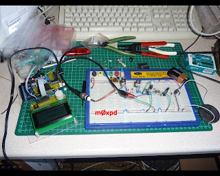
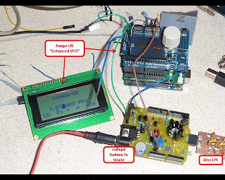
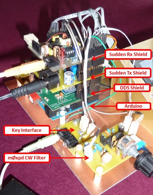
Now - before we go any further - let me be careful to explain that none of what follows is, in any sense, a criticism of the Sudden, the SA602/612, or anything else. It is just a story about my self-education and recreation.Here's my (very) ugly experimental system...
It is a fairly conventional embodiment of the "Sudden" - with the only exception being the fact that it is tuned using an MVAM109, ultimately to be controlled by a DAC (as described in
this earlier post) but here controlled by a stable d.c. source. Not seen in the photo above is the input RF network (more of which later).
I was surprised (
/shocked / intrigued / startled / depressed - call it what you will) by an unexpected aspect of the performance of the system, which has become the subject of the "living nightmare" I refer to above. The receiver was found to "chirp" very badly on receiving strong signals - CW, of course (
I have heard rumor there are other modes).
Some investigation with my old Racal-Dana Universal Counter Timer revealed that the VFO was being pulled by such strong signals. I didn't expect that!
I contacted George, who told me that he had "not heard of VFO pulling as a common problem" - and suggested that "The best route is probably the input attenuator".
A quick experiment confirmed that reducing the signal level did indeed stop the pulling - but I wanted to try to understand what was causing this unexpected behaviour - partly because I believe it must be one of the limitations on such a receiver's ultimate performance in dealing with weak signals on an overcrowded band, where consideration for not treading on the dainty toes of QRP signals isn't at the top of everybody's agenda.
I made a few experiments and arrived at what remains (for me) a rather surprising conclusion.
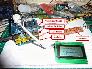
I started with a "vanilla" Sudden...
This system displayed the "chirp" on receiving strong signals and acted as a reference.
Next, I started to wonder what might be the mechanism behind disturbance of the VFO's action. The first thing I tried was to produce a stabilized power supply for the mixer / oscillator - as has been done with the "
Sudden 2"...
This made no significant difference - so I sought to increase the decoupling between the oscillator and the remainder of the receiver as much as possible.
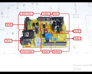
To achieve this, I buffered and amplified the oscillator signal (derived from the unused winding on the transformer, the other side of which was used as the oscillator coil) using my popcorn buffer module and used this to drive a second SA612, working only as mixer...
In this test, I also used a second LM386, distant from the SA612 used as oscillator, as seen in this photo...
This functional separation of oscillator and mixer between two SA612s and the physical separation between the oscillator '612 and the LM386 also persuaded me that the ability of strong input signals to pull the VFO - STILL PRESENT IN THIS TEST - was not caused by consequences of the "layout" of my circuit. I was baffled.
At this point, I speculated that there might be some coupling between the RF and AF stages - perhaps caused by the rather long speaker leads. So I replaced the speaker and its long lead with a 15 Ohm resistor, right on the LM386 output - with no change - the VFO was still pulled.
The system was being powered by a nice old Farnell linear power supply, with a big analog meter to monitor output current. I could see that the current increased (from around 50 to 55 mA) on receiving a large signal. I disconnected the loudspeaker (such that there was no increase in current - the additional current was all associated with driving the audio frequency load) AND THE VFO PULL DISAPPEARED!
The same - not surprisingly - was true if I powered down the LM386.
This really was odd - I could not measure ANY change in power supply conditions at the oscillator - the voltage was constant to better than 100 microvolts (i.e. better than one part in 50000), given the locally regulated 5V supply.
Then I tried provoking the same outcome (a change in VFO frequency) by changing not the input signal - but the AF signal. Previously, the increase in the AF power was caused by an associated increase in RF signal. Now, I tried driving the LM386 input with an AF signal, to dissipate the same AF power in the speaker.
I COULD GENERATE THE VFO PULL !!!I have no idea how/why this is happening - there is no measurable change at the oscillator's local power supply. It is driven by the same RF input. It is loaded by the same load impedance presented by a (powered but unloaded) LM386 - but it is still pulled when I apply AF from a separate signal source to the input of the other LM386.
[Note: whilst ordinary linear concepts like correlation and coherence don't have any meaning in the context of the non-linear operation of "mixing", bear in mind that the AF oscillator is independent of the SA612 oscillator and any RF going into it {I hope!}]
So - a living nightmare. The sense that reason is power-less. The frustration and futility of banging one's head against a hard object for too long.
All I can hope to do is present some evidence, in a form capable of independent verification (by YOU) and hope that you'll be able to shake me out of my bad dream. Here's the evidence...
I'll set up the vanilla Sudden once again - but with a 50 Ohm attenuator on the input, rather than the stock 10k potentiometer (
we're trying to deal with too many variables already here - I don't want the potentiometer changing the source impedance of the RF).
Here's my input arrangement - signals derived from the Norcal S9 Generator (or, rather, my "
sincerest form of flattery" version), going through a
switchable attenuator...
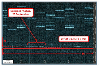
We'll tune the receiver and switch the input through 20dB - first with the speaker loading the LM386, as per normal use. The audio is monitored on Spectran...
You can see where I switch the level. You can see the consequence of the change (
the VFO frequency goes DOWN with increasing signal amplitude). The frequency change is about 30Hz, which assuming a reference of 650Hz, is a ratio of 4.6% which, for the musically literate amongst you, is close to a semitone (2^(1/12) is approximately 5.9%). In more extreme cases, I have observed frequency pulls exceeding 90Hz (greater than a whole-tone).
Now, if we disconnect the speaker (
leaving only the fairly high-Z load from direct connection to the computer soundcard) and make the same test...
Sure, the charming analog VFO is doing its wonderful slow "drift" thing - but it is completely agnostic to input level.
So - tell me - what does your Sudden do when you've got the input attenuator set too high?
Of course it distorts - but does its VFO get dragged around too?
I'd like to know - but I'd LOVE to understand WHY!
...-.- de m0xpd
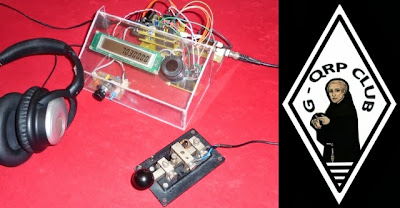
Post Scriptum:In the course of the above, I started to use the 10mm "Toko 10k replacement" coils produced by
Spectrum Communications and available (
to members) from the
G-QRP club.
I couldn't find these as an Eagle part - so I built one from scratch.
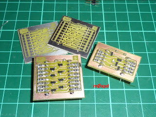
This allowed me to make up a PCB for a generic band-pass filter
(see George's recipe in the current number of SPRAT, vol. 154, p. 25).
Here's one made up for 40m...
I'll be pleased to share the library with anybody that needs it - only Cadsoft still haven't remembered me (
despite an email request sent over a week ago), so I can't post on the official download page (along with my
Toroid library for inductors and transformers wound on toroidal cores).
Get in contact directly if you want an early copy of my new "inductor-spectrum.lbr" library.