Quantcast
Channel: m0xpd's 'Shack Nasties'
Viewing all 220 articles
Browse latest View live

Automated IF Filter Measurement

$
0
0
Readers will have seen how I have used an Arduino to generate sweeps of the Intermediate Frequency of a receiver, allowing me to visualize the response of a crystal filter in situ. Well now - with the recent work on peak voltage detection associated with the "Power" meter - I've found myself in a position to automate more of the process...


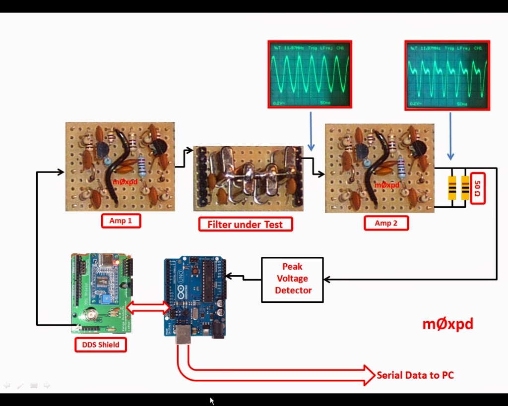
An m0xpd DDS shield generates a sweep of the IF range of interest, in controllable frequency increments (currently I'm using 50 Hz steps). Its output is fed to a broadband amplifier (actually one of the plug-in BITX amplifiers), which drives the crystal IF filter under test (in this case, it is the little 12 MHz plug-in module described previously). The output of the filter is fed to a second amplifier, which is terminated by 50 Ohms.

The immediate intention is that this copies the arrangement in the BITX receiver - as I want to be able to make in-situ measurements of the IF filter response in a BITX (for reasons that will become clear over the coming months). Surrounding the filter by the bi-directional amplifiers and the 50 Ohm termination (which copies the loading presented by the pi pad in front of the second mixer)  matches the conditions in the BITX. Later, this might develop into a more general "test bed" for measurements on any crystal filter.

The voltage developed over the 50 Ohm termination (actually realised by my here rather over-specified new dummy load) is sensed by my "power meter". The result is sent by serial link to a PC, for each frequency measured in the sweep. The results are sent in tab-delimited form, with the frequency sent first, then the peak voltage measured at that frequency (represented by the ADC code - although any other format is possible - and easy!).

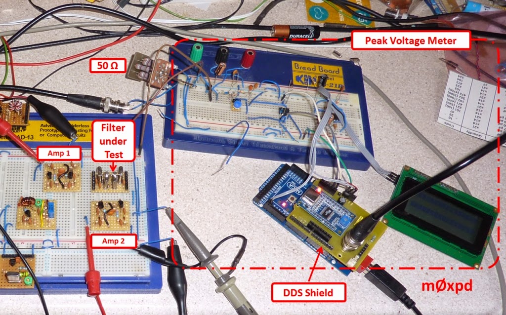
Here's the whole shooting match in the flesh...


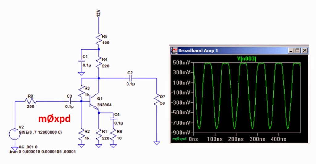
As you can see on the 'scope trace in the top right hand corner of the image right at the top of this post, the output of the second BITX amplifier is actually pushed into asymmetric non-linearity at this signal level, with its negative peak level significantly larger in magnitude than its positive.

This is exactly what's expected of this simple amplifier, as confirmed by this little LT SPICE model...


Of course, as (bad) luck would have it, your humble servant's peak voltage meter reads the POSITIVE peak voltage - I was rather worried that I'd lost a lot of dynamic range and that the system wouldn't work - but I pressed on...

The serial data from the Arduino can be read into any terminal program (PuTTY, Realterm, etc) - but I used the Serial Monitor feature within the Arduino environment for simplicity.

Here you can see (an extract of) the data read into the Serial Monitor, which is then copied into Excel (or your favourite spreadheet) for plotting...


The ADC code is the raw number read from the analog to digital converter (proportional to the peak voltage), which I've converted first into voltage, then into dB re 1 V ("dBV").

A plot of the magnitude frequency response of the IF filter is easy to produce...


As a further test of the system's flexibility, I switched my attention to an 8MHz IF filter I'd been using previously for CW applications and plugged it into the "Filter under Test" position...


I changed the start and end points of the frequency sweep in my code and ran a new test...


I knew this was a nice, clean filter - but I didn't know quite how flat it was!

This test takes about ten seconds to run. With a prepared "template" in Excel, it takes about another 10 seconds to copy the data from the Serial Monitor window into Excel and produce the graph!

The bare bones of my code are seen below - they're quite enough to communicate (as "pseudo-code") the intention of what I'm doing to anybody who wants to follow.

The code runs a sweep of frequencies (variable f), starting at fStart and running to fEnd, with an increment fStep. There's a delay of T milliseconds between each increment (on top of all the other tasks). The code uses my DDS library (of course).


Measuring the IF response of my SSB rigs in situ is now easily done, in less than a minute.

...-.- de m0xpd

Hats off to India

$
0
0
Having saluted China's achievements in space exploration it is only fair that we should also recognize another nation's entry into the elite club...

India today successfully placed an object into orbit around Mars - here's a graphic from the front page of the rightly proud Indian Space Research Organisation...


There is something extra-special about inter-planetary exploration that commands additional kudos.

Now we've demonstrated an inter-planetary capacity, perhaps we can inspire solutions to problems within arm's reach.

Well done India - hats off to you!

...-.- de m0xpd

Si5351

$
0
0
I've been wanting to get my hands on an Si5351 for months, excited by the prospect of three programmable oscillators in a tiny, inexpensive package. Well - today, it happened...

I got a couple of the nice little breakout boards from Her Ladyship, Limor Fried


As is usual for Adafruit products, this board is supported by an excellent tutorial and some software.

The tutorial support includes everything you need to know to get running with the Si5351 in an Arduino context (although the board can be used with other systems too) and the software is in the form of an Arduino sketch.

I had a MEGA lying on the bench - so I hooked my new Si5351 up to that (it needs just power and the two wires of an I2C interface)...


I downloaded the Adafruit library and example program and soon had the little chip squirting out square waves...


The Si5351A3 has three (independent) outputs and I only have a two channel 'scope here at the moment - so here are three channels captured on the ripoff logic analyser I purchased from Banggood the other day...


It works - but I have to say the Adafruit library is hardly "ready to use".

Fortunately, Jason, nt7s, has come to our rescue with a much smoother library which is also available for download from a GitHub repository.

I tried that code with the MEGA / Adafruit breakout combo and found it much easier to generate Ham-friendly RF.

Here's a 14 MHz signal...


which was set up very quickly and cleanly, as you can see below - all thanks to Jason's efficient library...


This is the way I'll be moving forward with the Si5351 - thanks Jason.

I wonder if I can drive it with the Arduino DUE.

...-.- de m0xpd

Si5351 in the BITX

$
0
0
Having played with the little Si5351 device in the Adafruit breakout board last weekend, I took the opportunity to build it into a VFO system and attach it to a receiver...

The new VFO was functionally a re-work of the dual DDS system I put together for my BITX at the tail end of last year, even sharing the same breadboard and Arduino NANO controller I used in early experiments...


On the breadboard you can see (from left to right) the NANO, a rotary encoder for tuning and the Si5351 breakout board. The LCD reveals that the system is running a modified version of my dual DDS code, which led to the SPRAT article with Pete Juliano, n6qw, "RF Generation for Superhets". This code generates both "BFO" and "VFO" signals - thereby making use of two-of-three of the available oscillators on the Si5351.

The system worked FB - so I hooked it up to my experimental "Breadboard BITX" receiver for a test. Again, everything worked perfectly (once I had set up the code's implementation of the BFO to the correct frequency for the particular 10 MHz IF filter I had mounted at the time).

However, the implementation of the "VFO" system on its own separate solder-less breadboard, seen in the photo above, was all a bit clumsy - so I exploited the simplicity and small physical size offered by the new Si5351 signal generator and tidied things up...


Above you see a complete BITX receiver (that's to say - only the parts required to operate as a receiver are present but all of them are fully bi-directional) on a single plug-in breadboard. Antenna input at "top left", speaker output at the bottom.

An annotated picture will save a thousand further words of description ("BA" = Bidirectional Amplifier)...


As you see, I made a new plug-in tuning module, hosting a rotary encoder. What is not so clear from the picture is that on each side of the tuning knob are push buttons that drive the remainder of the user interface (moving the "cursor" to select tuning rate, navigating the menu structure, etc).

The system seems to work every bit as well as before (as far as I can judge from a few minutes subjective listening in rather noisy band conditions on 40m) with the exception that there is a rather strident "noise" when it is tuned to 7.143 MHz the origin of which I can't explain. Also, I haven't yet done anything to optimise the level of the input to the amplifiers (and / or adjust their gain) I provided for the mixers I just stuck the signals from the Adafruit board straight in and saw what happened. Whilst the system is already working well, I suspect things can only get better.

There will be a release of the "Double DDS" code for the Si5351 - but I'm not yet ready for that. When it is suitable for public disclosure, you'll be the first to know.

This little Si5351 certainly is living up to expectations - I want more.

...-.- de m0xpd


QRP HomeBuilder QRT

$
0
0
Those of you who monitor the QRP-L list already will know that Todd Gale, ve7bpo, has taken down the QRP HomeBuilder website


This excellent resource has been a site of special interest to me over the years as the home of the Funster 40, which motivated my own Funster Plus rig.

Todd's work has always been of the very highest quality, being solid, evidence-based, honest engineering. It has been coloured in recent years by the introduction of some new dimensions of "comedy" or "character" which I don't claim to understand - but that doesn't change the core quality of Todd's offering.

Fortunately - although the website is no more - Todd has generously made an archive of the site available for download as a PDF. I don't know how complete that archive is - but it is there for all to capture, as I have done. Ironically, given that I referred to his excellent library for the Si5351 recently, Jason, nt7s is one of the people hosting the archive here.

Of course, QRP HomeBuilder is now removed from the links at the right hand side of is page - and the space that it has made in 'M0XPD's LINKS' has been occupied by Jason's 'Ripples in the Ether'.

We all owe Todd an enormous debt of gratitude for all he has done at QRP HomeBuilder - but, as Benard Ighner's song says,

Everything must change 
Nothing stays the same 
.... 
Nothing and no one goes unchanged 

Todd hasn't stayed the same - he has started a new initiative: Popcorn QRP , which takes its place in the links.

I look forward to continuing to learn from Todd's experiments.

...-.- de m0xpd

Julian, g4ilo, SK

$
0
0

Julian Moss, g4ilo, died peacefully on Friday evening.

His website and blog taught us all so much about radio.

His other blog taught us all so much about living.

Rest easy, Julian.

...-.- de m0xpd

Rishworth, SDRduino and the Si5351

$
0
0
Just back from the 25th G-QRP Mini Convention, where I disappointed the punters by presenting again. I broke up the monotony of my talk with some examples of "QRP" TV test cards and thought it would be nice to design a new one, featuring our beloved Franciscan...


My subject took the simple ideas of last year's "Occam's Microcontroller" project and stretched them to embrace Software-Defined Radio, whilst keeping it all within the Arduino family.

The idea was embodied in the SDR rig which you see below, mounted on a piece of scrap plywood from my youngest daughter's house renovation project...


This project will, henceforth, be known (with apologies) as SDRduino.

Those fortunate enough to have missed the talk can see my slides here.

The Si5351 generated quite a lot of discussion at the Convention and I promised to put up some code. There is now a version of the "RF for Superhets" code available from this Github repository. I've tested it on 40m on my modular BITX - but would appreciate any bug reports from early "beta test" users!

...-.- de m0xpd

Dodgy Si5351s

$
0
0
Dodgy (for the benefit of international readers) is an informal British adjective meaning "dishonest or unreliable", with further connotations of "potentially dangerous" and "of low quality". I have recently had a batch of dodgy Si5351s foisted upon me - caveat emptor!

You will have seen my infatuation with the Si5351 developing whilst she was clothed in the Adafruit Breakout Board. I was - quite naturally - keen to undress the device and play with her in the flesh.

Fortunately, a batch of naked Si5351s arrived. Unfortunately (given my poor eyesight and cack-handedness), I had first to deal with the "terrible miscalculation of scale" and mount the bare devices on MSOP-10 to DIL carrier boards...


Credit where it is due - I had the devices MOUNTED on the carriers - thanks, Nigel and Dennis!

With objects that I could now both see and handle, I could contemplate making an operating environment for them - I chose (not surprisingly) the environment of an Arduino shield...


Here (above) you see a socket ready to receive the Si5351, a 25 MHz crystal to clock it and a level converter circuit to translate I2C signals from the Arduino UNO lurking beneath the shield to 3v3.

The level-converter circuit is - ironically - the same circuit I used to perform the same role for the earlier, much beloved, Silicon Labs RF generator (the Si570). The same circuit I have used many times in my modular level converter plug-ins. Most ironically of all, it is the same circuit her Ladyship uses on the Adafruit Si5351 Breakout board.

Yes - dear reader - underneath those big labels there are some more pieces of circuitry which I am deliberately concealing from you. It isn't time to show you yet -  Pete calls this the "Fan Dance"!

I put the new Si5351s in the socket - my heart pumping slightly faster than its normal resting rate - and - nothing happened.

I tried all my code (which I knew worked, from experience with the Adafruit board). I tried all the "test" example programs (from Jason and Adafruit). Nothing.

In the end - in desperation - I tried running an I2C "scanner" program, which searches for the presence of any I2C device, and reports what it finds.

Here's what happened...


No wonder nothing was happening - the Si5351 code was anticipating a device at I2C base address of (hex) 60. Instead, the actual device appeared at 6F.

Let's be clear - this is WRONG. This is OUT OF SPEC. Here is an extract from the Data Sheet that defines what an Si5351 IS...


The extra commentary (in the red box) is from your humble servant. Our little 10-pin device only has one I2C address : 0x60. Fancier devices (with more pins) can use one of those pins to give an optional choice of 0x60 OR 0x61. But our little Si5351A is just specified to be there on 0x60. End of.

I knew that my shield with its level converter circuitry was working fine, because I could put the Adafruit Breakout board into the socket and the I2C Scanner could see the Si5351 at the correct address..,


Then - I discovered that the dodgy Si5351s would actually respond, as long as I modified the base address in the libraries to correspond to the (incorrect) 0x6F value that their hardware embodied. This is achieved easily enough in Jason, nt7s' library by an edit of one character of the si5351.h file. But it does nothing to recover the dodginess of the batch of rogue devices...

I want to use Jason's library with ALL my Si5351s - I'm not prepared to have two different versions of software "drivers" to handle some real devices (on the Adafruit boards) and some dodgy ones. This has to be about interoperability.

Finally, I got a second batch of Si5351s and had them mounted on DIL carriers. I put them into the shield and ran the scanner...


At last - the real thing!

Batch 1 came from Mouser (UK). Batch 2 came from Digi-Key.

Jason, nt7s, has previously blogged:

"it seems obvious that Mouser has some oddball parts; perhaps they were custom parts that inadvertently escaped Silicon Labs. I'm still waiting to hear back from Mouser about the issue, but in the meantime, I would recommend you order from a different distributor until they fix this problem."

The evidence above shows that parts from Mouser in the UK also display the same dodgy behaviour.

At the time of writing, Mouser have kindly agreed to refund the purchaser of the Batch 1 devices.

I can continue my romance with some pukka Si5351s.

Pukka, (for the benefit of international readers) is a informal British adjective, meaning "first class" or "genuine" and having Hindi and Urdu origin, (where it originally meant "cooked, ripe").

...-.- de m0xpd


Taming the Rotary Encoders

$
0
0
My Rotary Encoders have had it easy - it is time to introduce some tough love...


Ever since the earliest days of the Occam's Microcontroller project, the Arduino QRP transceiver that preceded it (or even the earliest games with the Raspberry Pi) I have used a simple software interface to my rotary encoders. Critics could (with some justification) call it a lazy software interface - but I will defend the word "simple"...

All my (Arduino) code observes the state of the rotary encoder switches once per "loop". This has the considerable benefit of simplicity (as advocated by the KISS principle, by our belovéd Franciscan, etc). It also has the considerable risk of inadequacy!

If the encoder is to be read accurately, it must be sampled sufficiently frequently. One danger of my "simple" approach is that the "one observation per pass through the loop( )" will not constitute a sufficiently high sample rate to satisfy Shannon's sampling theorem, such that neither direction nor speed of the encoder can be deduced. Errors will result.

Both the "correct" solutions (fast, interrupt-driven sampling of the encoder or explicit connection of the encoder to inputs with edge transition detection capability which can trigger interrupts) feel way-too complicated to me and offend against my sense of "appropriate engineering". But the simple approach was always known to be standing on thin ice - that ice has just melted, forcing me into action. Two things prompted my activity...

Firstly, I was getting errors from the Rotary Encoder in my own rig.


I could understand this - my rig was running way-bigger code than anything I'd released to the public (there's more in there than I've told you about - YET!), so my own "sample rate" was even lower than that of any of my "customers". Also, I had a rather long cable run from my board to my Rotary Encoder and I had a pretty hostile operating environment. Most importantly of all, I could readily ignore complaints from this source - even though the errors from my encoder were getting to be pretty bad!

The second thing that happened was much more significant - it really catalysed ACTION. A real, live reader of this blog, named Richard, came up to me at the Rishworth mini-convention and described the problem. He didn't complain - but he could (and perhaps should) have done.

In response to Richard's input, I've finally done something, which has fixed my own rig (above) and which seems to offer a useful "taming" of the Rotary Encoder - I've added two capacitors!


The capacitors are placed in parallel with the two "switches" in the rotation sensing part of the encoder, as shown in the schematic above.  In fact, I had tried this previously (in building the encoder system for the "VFO" for the SI5351-based BITX), where I found it to work very well.

Action of the additional capacitors is understood if you remember that there are resistors (shown dotted in the schematic above) - either fitted explicitly as extra components or embodied as internal pull-ups in the microcontroller. The combination of these resistors and the additional capacitors are going to define a time-constant (making appropriate choice of the capacitor value dependent upon the resistor) which modifies the switching action as sensed by the microcontroller...

The sketch below shows one switch closure with- (bottom) and without- (top) a capacitor fitted.


The downward transition isn't changed. But when the switch opens, the capacitor has to be charged to build up the voltage, introducing a time delay Δt before the voltage read on the microcontroller input pin reaches the logic high value. This "stretches" the pulse width. If the pulse is stretched wider, it can be observed successfully at a lower sample rate.

The capacitors also modify switch bounce (although I think this is irrelevant, given my lamentably slow sample rate) and suppress high-frequency noise which might be induced on the otherwise high impedance line.

I can't confirm the exact mechanism that is taming my Rotary Encoders - all I can report is that the addition of the 100nF capacitors, as shown, is doing an excellent job. I recommend that you add them to all the m0xpd rigs, VFOs, etc that use Rotary Encoders read by Arduino software.

Thanks Richard!

...-.- de m0xpd

Update (16 Nov)


Fred, wa1dlz, has been experiencing problems with my code, including the problem with the Rotary Encoder - see his comment below. In subsequent private correspondence, Fred told me that the capacitors described above made no difference at all on his system - in fact "the 100nf caps actually made things worse".

This information from Fred prompted me to try to visualise the "stretch" in the pulse from the rotary encoder to confirm that it actually exists.

I set up a system (running the "Double DDS" code) and instrumented the rotary encoder pins using my ripoff logic analyser. This claims to interpret VHIGH as being anything greater than 1.4V.

Given that the pulse widths from the encoder are controlled by the rotation speed - which itself is controlled by my hand - the entire experiment is rather difficult to construct. I decided to use one "side" of the encoder as a reference and to add the capacitor to the other "side", as suggested in this schematic...


The resistors (as shown dotted above) are the internal pull-ups in the ATmega328P microcontroller.

I made several measurements, in which I sought to rotate the encoder at roughly similar speed, with and without the capacitor Cx.

The following results are representative...


Whilst I don't suggest this is marked by rigor, I do think there is indication of an increase in the relative width of the "off" phase of the B signal as the capacitor Cx is increased.

Fred's findings show that the capacitors are - by no means - a panacea. They haven't helped him at all -but they have transformed my rig's tuning control from a frustration to a joy.

The "stretch" seems real.  But it may not stretch to solving your problem - please let me know, one way or the other!

Swedish Encoder Taming

$
0
0
Leif, sm7mcd, has sent me some great photographs of his experiments using capacitors to tame the output of rotary encoders - and he has given given me permission to publish them here...

Leif starts by showing that the encoder is capable of generating perfectly clean output in clockwise rotation...


However, the same encoder can also generate "glitches" in its output as the switch contacts bounce, clearly seen here...


Similarly, in counter-clockwise rotation (notice how the bottom quadrature trace now lags the top trace, indicating the different sense of rotation), clean output is possible...


but the switches can also bounce with the resultant glitches...


Leif has added some (enormous) 100nF Mylar capacitors...


and this generates the sort of pulse shape I suggested in the previous post...


Leif shows how the capacitors "eliminate" the glitches caused by the contact bounce...


Notice that the switch's bouncing closure does not have chance to discharge the capacitor and pull the voltage down to zero - we would need to include a discussion of the (small) switch contact resistance and the equivalent inductance in the circuit to describe this behaviour.

Certainly, as I commented in my last post, and as Leif's photos beautifully demonstrate, the capacitors "modify switch bounce". They also add the clear exponential shape to one side of the pulse which (with the addition of the threshold operation in the logic) gives the pulse width increase. 

I remain unsure of the exact mechanism that is taming the encoders - I do not know for certain if it is about switch bounce or pulse width. But I quote from Leif: 

"I experienced the same problem with reading errors from the rotary encoder and it's nice to see that we found the same cure. I did some testing in rapid spinning of the encoder and I found 100 nF almost optimal also for real rapid spinning."

Leif is a member of den Kalmar Radio Amatör Sällskap (Kalmar Amateur Radio Society), who are using some of the m0xpd / Kanga shields in their projects this year. I'm looking forward to any excuses for collaboration with Leif and his fellow members of KRAS.

Tack så mycket, Leif 

...-.- de m0xpd


Arduino SDR 3

$
0
0
When I was pulling together the "slides" for my recent talk on the Arduino Software-Defined-Radio at Rishworth, I realised just how long it had been since I had touched the code - or, indeed, any technical aspect of this interesting radio. I had, indeed, left undone what I ought to have done.


I decided this weekend it was time to make amends - I started by practicing what I have preached over the past few posts and added some 100nF capacitors on the tuning rotary encoder...


That trivial job done (and tuning duly improved -  although the SDR is not as good as my other rigs as the processor is groaning under a close-to 100% computational load), I went on to awaken a dormant "feature" of the code: the ability to implement variable receive bandwidth.

Early in my relationship with the Arduino DUE, I described experiments with variable bandwidth filter design. I used this same filter design routine - at IF - in my software-defined radio experiments. Previously, I never exercised the capability to interpret the edges of the bandpass filter in the radio as variables. Now, it was time to warm that feature up...

I had previously used an analog input on one of the ADC lines of the DUE to control the filter design algorithm - this was repeated in slightly modified form with the double (quadrature) inputs from the Tayloe detector...


My code reads the voltage developed on the bandwidth control potentiometer into a variable called POTO. If this does not change, the code doesn't respond. But if a change is observed, the new voltage is read and used to design upper and lower frequencies for a bandpass filter.

At the lowest setting, (POTO = 0) this will yield a VERY tight CW filter, centred on 600Hz. On the widest setting (POTO = 4096), this will yield a VERY wide SSB filter.

Here's the code that responds to the POTO values...


[No - I'm still not showing you FilterDesign( ) !!]

The rig is no longer "shackled" to a PC - but I can still connect a computer to the USB port for programming and diagnostic duties. That's why there are Serial.print( ) calls in the code segment above. Here's what happens when I adjust the new bandwidth control...

If we steal something like the "hairpin" crescendo / diminuendo idea from musical notation and rotate it through 90 degrees (see the red lines below), you can see what happens when I increase bandwidth from "normal" to "wide" SSB and back again...


Similarly, you can see what happens when I pull back to a really tight CW bandwidth...


All this is all very well - but what does it SOUND like?

Well - I know from the earlier "baseband" (that's to say, audio frequency) filter experiments that the filtering works and sounds fine. But the filter design takes a finite time - so filter re-design isn't instant. Accordingly, I tried stopping the audio when the filters were re-designed, by turning off the interrupts. That made a clear break in the audio, which was pretty disruptive.

Then I got bold and just let it happen. Sure  - you can hear an odd "digital" noise when the filters change, but it isn't objectionable. In fact, it is much LESS objectionable than muting the signal,

Then I decided I would try to make a recording, so you could hear it. I set up to record dj2xb reading the RSGB news this morning on 40m. But there was all sorts of trouble and the beginnings of a Anglo-French war over some ungentlemanly QRM that I decided not to dignify by recording.

You'll have to wait to listen to the sound of my variable bandwidth system - suffice to say, it works.

Here is the new bandwidth control, implemented - for the moment - on a little trimmer.


More to follow - I'm beginning to enjoy playing with SDR again!

...-.- de m0xpd

Vintage Microprocessors

$
0
0
Whilst preparing some slides for a talk, I needed a picture of my first microprocessor which (I have to admit) was the General Instruments CP1600.

I was surprised to find the internet isn't exactly falling over itself with images of my "first date" - but there is an old example here in the junk box. So, by way of a public service, here's some vintage micro "porn"...


The nMOS CP1600 had an unusual 16-bit architecture, which it inherited from the PDP-11 minicomputer.

The spotty, teenage proto-m0xpd saved his pennies and purchased a CP1600 from Watford Electronics (it was far too exotic to be available from anywhere in Luton back in the 70s),

Here's Watford's logo and storefront...


I got my CP1600 to build a "computer" which was described in one of the magazines of the day - Practical Electronics or something similar. A quick internet search hasn't identified which magazine it was (if any readers remember - please let me know).

All I can remember of that computer is that I was too poor to be able to afford 16 switches to enter data - so I started off with an array of 16 pairs of 2mm sockets (one for logic "true" and one for logic "false") and 16 2mm plugs on short flying leads. The "switch array" was very much in the style of the PDP-11 (at least it would have been, if I had been able to afford switches).

Oh yes - one other thing - my computer had 256 words of memory. Those were the days.

The dalliance with the CP1600 was short-lived - I soon converted to the 6502 (the cheapskate's choice) here's a later example (evidently from RadioSpares)...


Interestingly, General Instruments "became" Microchip - I was to spend even more time playing with their products.

Now there are the sophisticated  distractions of Atmel and ARM etc - but I still enjoy looking at pictures of the simple, exciting processors of my youth - and I still have some of them here, hidden away, but "living with me". Don't tell the XYL!

...-.- de m0xpd

Directly Observing Radio Reception

$
0
0
I've messed with instrumenting (or, at least, visualising) IF behaviour before but now I've decided to stop messing around with just one part of the receiver chain. I want to observe the WHOLE reception process process directly - from RF in to the antenna input of a radio all the way to AF out of the amplifier...


My scheme uses the (inevitable) Arduino and DDS combo to generate an RF sweep, which is attenuated and passed directly into the Radio under Test. The resulting output voltage to the speaker (or headphone) is sampled by an RMS to d.c. converter and read back to the Arduino, which reports both the RF frequency and the level of the generated AF signal to a program running on a host computer, such that a graph can automatically be produced...


I have implemented the Arduino / DDS combination using a MEGA and an early prototype m0xpd DDS shield I had lying around...


My initial tests today have been for lower side-band on 40m, so I arranged for the RF sweep to be DOWNWARD from a start frequency, FStart, for a span of 10 kHz in 50 Hz steps. The Radio under Test would be tuned to FStart, such that the resulting AF output should be an UPWARD sweep from 0 to 10 kHz (more explanation below...).

The code was a simple hack of my earlier sketch for the IF work.

For the sake of speed and convenience, I implemented the RMS to dc conversion (what we might also call "detection") operation using a Bruel and Kjaer Electronic Voltmeter (seen in the image at the head of this post), which conveniently has a d.c, output proportional to its meter reading. The d.c. output was fed straight into pin A0 of the Arduino.

My first tests were made on the "Breadboard BITX" radio...


A processing sketch running on the PC initiated the sweep on the Arduino and collected and graphed the response data, which is shown below...


This is the overall receiving response of the radio from RF to audio, measured and graphed automatically with an (approx.) S9 input in about 15 seconds! Note that it is not "calibrated" in absolute "sensitivity" terms - I'm interested only in the shape of the receiving response.

See how the frequency axis is labelled as running DOWN from FStart at 7,117 MHz to FEnd at 7.107 MHz. This downward sweep of RF is interpreted by the radio, tuned to 7,117 MHz in lower side-band mode, as an upward sweeping audio tone - which is why the graph above is formatted the way it is. 

Think of the frequency axis as being not only the (falling) RF axis (seen at the bottom of the figure below) but also - equivalently - the (increasing) AF axis (seen at the top of the figure below) ...


OK - now I've got this handy new trick, I can use it to prove to you that my Arduino SDR radio's Rx bandwidth really does change - just as I claimed last weekend.

I set  up the Arduino SDR rig as the Radio under Test...


and put a voltmeter on the wiper of the potentiometer that generates the control voltage for Rx bandwidth. Then I made a bunch of receive bandwidth measurements at increasing settings of the control voltage...


As you see, there's a nice smooth increase of Rx bandwidth with increasing control voltage, all the way up to the maximum.

Last of all (for the moment) I took out my multi-band, BITX-inspired development platform and set it up for 40m...


I was quickly able to confirm what is obvious from listening (particularly after listening to the breadboard BITX or - even more so - the SDR): the receiving bandwidth is too narrow...


This is a great way of directly measuring the overall response of a radio system - warts and all - all the way from incoming RF to the output to the speaker. It works like a dream. I am going to neaten it up - possibly by replacing the Bruel and Kjaer element with a custom piece of electronics and by making the RF side a little more "formal" - because I have some important tasks for this new measurement technique in the near future.

Watch this space!

...-.- de m0xpd

Continual Interruptions

$
0
0
This is the story of doing the job properly: tracking the rotation of rotary encoders using an interrupt-based approach. The story leads to updated versions of the m0xpd VFO code for AD9850 and Si5351 systems.

I have explained how a desire for simplicity kept the early designs published on this blog based on a simple "polled" rotary encoder architecture. In truth, there was a little more to it than just a "desire for simplicity"...


The Kanga / m0xpd DDS shield has a user-configurable pin assignment for the DDS module pins. However, it is biased towards the use of pins D2:D5 - these are the easiest pin allocations to make, as you see in the photo above. This will use up the pins D2 and D3 on the Arduino UNO which are the only two which support hardware interrupts. Accordingly, the systems which used the DDS shield tended to occupy pins D2 and D3, making interrupts inaccessible.

Ever since the appearance of the Dual DDS scheme and, specifically, its embodiment in the R(F)duino, I have intentionally freed up pins 2 and 3 for the Rotary encoder in my own builds, with the intention of - one day - moving to an interrupt-driven interface.


That day has arrived.

Its arrival was ushered in by two additional factors. First was the appearance of the Si5351, which sits on the I2C interface and completely frees up all the digital pins originally squandered on the DDS module. Second - and most important - was inspiration from Tom Hall, ak2b's beautiful receiver, which I saw on Tom's You Tube video. Correspondence with Tom finally persuaded me I HAD to act...

The problem with the original "polling" interface is one of visibility - the encoder is largely invisible to the code.

It is as if the encoder is obscured behind a brick wall, glimpsed only for an instant within the course of each execution of the main program loop, through a gap in the wall...


The code executing in the continuous "loop" function passes this "gap" in the wall only once per cycle and has to look for a change in the encoder's state since the last time the device was polled. It is seen that there is a rather precarious dependence upon the time it takes for the other tasks which the code has to perform in the one pass around the loop (and, hence the sample rate) and the speed of rotation. This explains my recent preoccupation with capacitors on the encoder output!

The code associated with this polling approach is not elegant, dealing - as it must - with the consequences of the two possible changes in observed state...


By contrast, the interrupt approach allows a complete brick wall between loop( ) and the encoder, but establishes a second process - the Interrupt Service Routine ('ISR')- to count the pulses from the encoder.

The ISR has 20:20 vision of the encoder.


In my implementation, I've arranged for the Interrupt Service Routine to maintain a variable, "Turns", which counts the number of "clicks" from a start time until reset. Clockwise rotation adds to the count, whilst counter-clockwise subtracts...


In the new code, the main program loop (which, in the user-friendly world of the Arduino, is called "loop( )") has vision of the count variable, "Turns", AND can reset it back to zero.

The frequency adjustment routine, equivalent to the one above, now becomes...


Notice that if more than one "Turn" event occurs in one pass through the loop( ) it is is now handled correctly, rather than just counted as one (or missed altogether). Accordingly, the frequency adjustment (etc) is very much smoother.

The new interface to the rotary encoder depends upon an Arduino library, Rotary, which can be downloaded from Przemek, sq9nje's Github repository.

I have used the new interrupt handling approach to produce a revised version of the Dual DDS VFO code and the Si5351 VFO Code, both of which can be found here. Reports, please, from anybody who tries them (I've tested "personal" versions of these new interrupt-driven programs with great results in my own rigs, including the Breadboard BITX and the Multi-band rig).

The same methods can be used by readers who wish to modify any of the previous m0xpd systems (such as the Occam's projects or the Kanga VFO systems) but this will require re-allocation of pins 2 and 3 which presently are assigned to the DDS - a simple enough task.

...-.- de m0xpd

Parallel IF

$
0
0
Now that the January 2015 number of RadCom has started hitting the newsstands (even though I'm still looking forward to Christmas), I guess the cat is out of the bag...


The journal contains my article "A parallel filter architecture for flexible IF processing" (page 78) which - in turn - prompts me to reveal the true identity of the rig which I have been struggling to conceal in these pages for the past year.

What I have been clumsily calling the "multi-band rig" or (worse still) the "multi-band, BITX-inspired development platform" is, in fact, the Parallel IF rig...


I explain in the RadCom article how and why two ordinary crystal filters with disjoint pass-bands can sit next to each other - in parallel - quite comfortably. If these filters have different bandwidths, the whole rig can change receiving bandwidth simply by using the appropriate IF frequency required to select one or other of the filters. NO SWITCHING of any kind is required - just a change of oscillator frequencies.

You can imagine how easy this change of oscillator frequencies is to achieve with the RF Generator scheme that Pete Juliano and I already have published in SPRAT 158 and described in many blog posts, as summarised on this page.

The Parallel IF rig pictured above has two such crystal filters, between two of the ordinary bidirectional amplifiers familiar to builders of the BITX...


You can see my embodiments of these filters in the following photo, in which you'll note the absence of switches, relays and the like...


The software of the Parallel IF rig is a super-set of the m0xpd "Dual DDS" code - it includes an additional menu option to switch between the two IF frequencies required to operate one or other of the IF filters.

It is presented (of course) simply as a choice between the two receiving bandwidths...


The scheme works - very well.

Two weeks ago I presented a method for directly visualising overall receiving response - from RF to audio (magnitude) frequency response. Now you understand why!

With the disclosure of my new Parallel IF architecture, it is now time to use the new measurement method in anger...

Here's the measured response of the Parallel IF rig in SSB mode (a result you've already seen)...


Here's what happens if you keep the tuning the same but "switch" to the alternative IF path, giving a tighter overall response, appropriate to CW...


Formally, this is what might usually be called CW(R) mode as it is in lower side band; CW is more usually received in USB - this is just a convenience associated with the technique I've used to send CW from my rig, as described in SPRAT 159. The method works just as well with CW in USB - but would not allow a direct comparison with LSB reception in 40m, as above.

RSGB members can learn more about the method from the article in their copy of RadCom - other readers will be hearing very much more about the method over the coming months.

I am honoured to be working with Pete Juliano, n6qw, on the development of a new rig - a project specifically to showcase this "Parallel IF" principle. We will be publishing construction details of this new rig in 2015, hopefully in QRP Quarterly (subject to confirmation).

I am further honoured to have been invited to speak at QRP ARCI's Four Days in May 2015 - "the biggest and best QRP event in the World" (at least it was, before they invited me along HI HI).


You will not be surprised to hear that my subject will be this new method of achieving variable receive bandwidth in simple superhet rigs at very low cost.

I'm excited about it!

...-.- de m0xpd

R(F)duino DUE

$
0
0
An idle moment this weekend gave me opportunity to upgrade the R(F)duino to include the Si5351...


You've seen the original R(F)duino with its brace of AD9850 DDS modules, doing fine service in the Parallel IF rig. That system, being first, now should be called R(F)duino "UNO" (not that we're being influenced here).

Readers will know that I'm keen on the little Si5351 device, which offers a number of advantages over the AD9850s. Having already used the Si5351 in my RF generator scheme in the Breadboard BITX, I was keen to make a custom system - thus was born the second R(F)duino - the "DUE"...


As you see, I took very much a "minimum effort" approach to development of the DUE, simply plagiarising my design for the greater part of the UNO and swapping out the left hand side (as seen in the orientation above). The board has stayed at its rather large size for two reasons - first to accommodate all the connectors and second to make an easy retro-fit into the Parallel IF rig!

The features of the R(F)duino DUE are highlighted in the following annotated picture...


The schematic is here...


The code is essentially the Si5351 code that already has been published (but with extensions to support the Parallel IF functions, band change and SSB / CW transmit, which are some of the extra features of my transceiver). I couldn't resist differentiating it with a childish change of the banner line, just for this photo, taken during testing...


Now I need another idle moment or two to swap out the old R(F)duino in the Parallel IF rig for this new, improved, DUE version. I've just looked at the Christmas double issue of the Radio Times - doesn't look like there will be any trouble finding idle moments!

...-.- de m0xpd

Arduino SDR IV

$
0
0
Time to try once again to squeeze a quart into a pint pot...


One of the failings of my Arduino SDR, with its limited (12-bit) input stage, is the tendency to be swamped by big guns. The resulting distortion is of the particularly ugly "digital" variety that takes no prisoners.

At present, I'm dealing with this by knocking my ATU way off tune whenever a strong station comes on - but this is hardly an elegant solution.

Sure - I could add a simple potentiometer on the RF input - but that would never be addressable by anything other than my hand - barely an improvement over the ATU approach. I thought about adding a digital potentiometer at the RF input - but a quick look at the data sheets reveals that this approach is a non-starter.

Accordingly, I decided to play with a digital potentiometer in the "IF" of my software-defined radio which (of course) is actually in the high audio frequency range.

I happened to have an AD5242 in the "junk box" - as used in the experiments with the Digital Tube Screamer. This is a two-channel device (I needed a two-channel device to scale both the In-phase and Quadrature components of my system). The particular AD5242 in my collection was the 1MOhm variant.

The device features an I2C digital interface  - which was a bit of a concern, as I'd never had much joy with I2C and the Arduino DUE.

Fortunately, Rob Tillaart's library seemed to compile fine for the DUE and worked pretty much first time (once I had figured which of the two available I2C interfaces on the DUE was being used, with the help of my Ripoff logic analyser). I soon had the DUE talking to the AD5242 and implementing various resistances, tracking d.c. voltages read from a potentiometer...


Having confirmed I could control resistor values at will from the DUE, I thought about building a twin-channel, variable gain amplifier. It uses another Analog Devices chip from the "junk box", this time a quad OpAmp, which will run on a 3v3 supply - the AD8608...


Now, the physical potentiometer generates a voltage which is read into the DUE and then generates a control code to set the GAIN of the amplifiers. This gain varies between 6.5 dB and -41.5 dB. The (partial) schematic below gives you an idea of what I'm up to...


So - now the variable gain amplifier is added into the SDR receiver's input path...


It is, as you can see, very much a temporary "lash-up" at this stage. But it works fine. I have the ability to take shelter when the big guns open up. I also have a little more gain available to increase overall sensitivity. Plus, I've retained the variable receive bandwidth control from before.

But what - you might ask - is the advantage over putting the potentiometer on the RF input, just as I mentioned at the top of this post? Well...

One day soon, I will be able to allow the DUE to take over control of the AD5242 - to give automatic level control.

For the moment, I'll satisfy myself with manual control and focus on those other distractions the next few days have to offer.

...-.- de m0xpd

Si5351 Shield

$
0
0
I'm excited to bring news of a new board - a flexible RF Generator, based upon the Si5351, including two channels of amplification and a quadrature generator...


The board is served up in an Arduino Shield format - but it can be used as a general-purpose board with any system. I've been playing with the design for a few weeks now and I'm delighted to tell that it is a real team effort. As before, all this is made possible by Dennis, g6ybc, of Kanga Products but this time we have been joined by Pete Juliano, n6qw.

The prototype PCBs were delivered to Dennis just before Christmas and it gave us just the excuse we needed to meet up (in a pub, of course) to exchange greetings and components...


I soon had the digital side of things checked and working (but I must give credit where it is due - Dennis soldered the tiny Si5351 onto the board) and I was able to confirm operation two days before Christmas.

You can see the part-built system in its test configuration atop an Arduino UNO here...


The system in this state is, in fact, pretty much a functional duplicate of the experimental Arduino shield I've described before.

The 2*6 header at top left of the photo above is an expanded version of the "RF Bus" on the Kanga / m0xpd DDS Shield, to give backward compatibility between this new RF Generator and the old DDS Shield (along with the other shields that interfaced to it). The expansion allows for the fact that there are now three independent frequencies on the bus - and I've made not only the Q and I available on the header (as on the DDS Shield) but also their complements, Not Q and Not I.

The red jumpers (bottom right in the photo above) select the I2C source - putting the jumpers in place connects the I2C signals to pins A4 and A5 on the Arduino shield (as is appropriate to e.g. an Arduino UNO) whilst leaving them off makes the I2C available on header pins, to be allocated as the user wishes.

I finished stuffing the rest of the board yesterday and winding the coils, as seen in the photo below, in which I'm making an analog test from one of the n6qw output amplifiers...


The shield has all three outputs of the Si5351 accessible on the header, as I've already explained, but two of them are further buffered by amplifiers designed by my friend Pete - aptly described as "afterburners" by Bill, n2cqr. Readers will understand why I'm interested in having two channels so buffered, given my interest in Dual DDS schemes etc..

The outputs of these amplifiers are isolated by transformers and are available on 0.1 inch headers - or on the mandatory SMA connectors if you're feeling flush!

The whole shebang is explained in this annotated picture...


We need a few minor board revisions before we're ready to go public (they really are revisions, rather than corrections) and then you will be in a position to try it for yourself.

2015 looks like being an exciting year.

...-.- de m0xpd

Si5351 and Raspberry Pi

$
0
0
I promised that my new shield could be "used as a general-purpose board with any system", so I thought I better put my money where my mouth is. I also thought it would be nice to re-visit the Raspberry Pi...

A quick search turned up this "library" (actually it is in Python, where such things properly are called "Modules") for driving the Si5351 from a Pi. I decided to give it a spin - so I (literally) dusted off my Pi.

First, I had to learn how to use I2C - which I'd never done before on this platform. Actually - that's a lie: first I had to remember how to log in to the Pi, but we won't embarrass ourselves by revealing that truth!

Firing up I2C in Raspberry-land involves a few easy steps, which are reasonably well covered in (e.g.) this instructable. If, like me, you have a 512MB Pi, note that the I2C channel is number 1 (not 0, as given in the instructable referenced here - and many other "how to" resources on the net).

Once you get all the soft resources in place on your Pi, you're in a position to make the hardware connections to the GPIO pins  (SDA is pin 3 and SCL is pin 5 on my RPi model B). I used my fancy GPIO breakout, of course.

My first experiment used the Si5351 on the Adafruit breakout board - which you can see in the photo below...


With this hardware in place, I was able to test the I2C connection with the "I2CDETECT" command, which showed the Si5351 reporting for duty in her correct place (at 0x60)...


In the screen grab above, you can also see my call to the little program I wrote to set up the Si5351, using the resources in the "library" - man, was that a pain! This "library" is is re-work of the Adafruit (Arduino) library for the Si5351 (the quality of which I've commented upon before) and this resource is even weaker. There is pretty much zero documentation - so the little program below is just my very poor attempt to get something to run - which it manages to do...


Having satisfied myself that I could drive an Si5351 from the RPi, I hooked up the new prototype board. I emphasize there was NO ADDITIONAL INTERFACE HARDWARE USED - the new board can interface directly to the Pi or any other system - even with 3v3 logic (such as the Arduino DUE).

Here's the system on the bench - the Arduino UNO at top left of the photo was used to source the 3V3 and 12V  to power the new board (the RPi's 3v3 output is only rated to supply up to 50 milliAmps and - of course - there's no 12V supply).


The screen grabs from the RPi desktop were made using the (comically named) "SCROT" and emailed to the computer on which I'm writing this drivel. Whilst this method works, it does seem awfully inefficient (having the image take a long detour through the internet when the two computers are only inches from one another). So - I took the opportunity to learn about installing a Windows-compatible network "share" on my Raspberry Pi. This is made possible through a program called Samba, which works very well.

The morals of this story are:
1) The new (prototype) Kanga / m0xpd / n6qw board works FB with the Raspberry Pi
2) Thank God for Jason, nt7s' EXCELLENT Si5351 (Arduino) library
3) There is (as far as I know) a gap in the market for an equivalent library / module for the RPi
4) Maybe - just maybe - I'll order that Model B Plus and/or a Model A Plus

...-.- de m0xpd

Tuning Module

$
0
0
It is time for some beta testing of the new prototype Si5351 board and I need to distribute some to colleagues. To simplify that task, I have prepared some complete "VFO" systems...


As you see, there's the standard LCD display on an I2C interface, the new Si5351 board hosted on an Arduino UNO and a new Tuning Module, with the rotary encoder and the two push-buttons required to drive the input side of the user interface (familiar to anybody who has looked at one of the m0xpd rigs or the Kanga VFOs).

The Tuning Module isn't exactly a new idea - having already seen the light of day in the breadboard BITX - but this seems the easiest way to get a complete system up-and-running (more importantly, a number of identical systems spread across the world).

Here - for anybody who would like to do something similar - is the approach I took. I used stripboard, this time with the copper strips facing up, as I could only lay my hands on tactile switches in surface mount format today.


Here's a close-up of one of the tuning modules - I'm too cheap to supply a knob!


I've made the modules in two "editions"; one as shown above with a connector for a cable and one with pins intended for plugging into a solderless breadboard (of course)...


These aren't pretty - they're not supposed to be (as they're just for test purposes). But they show just how little is required to get the complete Parallel IF VFO system up and running.

...-.- de m0xpd

Viewing all 220 articles
Browse latest View live